
Related Manuals for Ole C2020

Summary of Contents for Ole C2020
- Page 1 O.L.E. (UK) Ltd C2020 INSTRUCTION & INSTALLATION MANUAL Revision: 01 Date: 27/04/2017 PD02/0005...
-
Page 2: Table Of Contents
High Accuracy Calibration Adjustments.................... 8 Troubleshooting ..........................8 Operation Instructions .......................... 9 Overview ............................9 Appendix 1 (C2020 Wiring Diagram) ....................10 Appendix 2 (Accessories) ........................11 B8 – Bund Probe / Level Switch ...................... 11 B2 – Water Sensor .......................... 11... -
Page 3: Introduction
Introduction The Purpose of this document is to outline the installation and operational procedures and the operation of the C2020. Safety Warnings To avoid injury please read this manual carefully before installation. Failure to do so could result in injury or failure of the equipment, this will invalidate any warranties given. -
Page 4: Installation Instructions
Installation Instructions Mounting Holes There are 4 mounting holes in the base of the unit (indicated with the Red Circles). These are located behind the front panel screws The distance between mounting holes is 110mm wide X 160mm high. Page 3 of 11... -
Page 5: Input Connections
Voltage or Current Output Connections 0v +V GND SIG +V Alarm Current Output Loop Passive Output Analogue 4-20mA Passive = Externally Powered (Needs Wire Link) Loop = Powered by C2020 (No Wire Link) Passive Set Jumper Accordingly Loop Page 4 of 11... -
Page 6: Power Input / Output Connections
Power Input / Output Connections WARNING Before applying the power, DOUBLE CHECK all the connections to the inputs and outputs. 100 – 240v AC Maximum Current - 0.7A Probes New Probes Legacy Probes New Probes Legacy Probes C23 = 3.0m Sensor with 10m of cable C22 = 2.5m Sensor C25 = 5.0m Sensor with 10m of cable C27 = 10.0m Sensor with 10m of cable... -
Page 7: Gauge Configuration
Gauge Configuration. To Calibrate the Gauge, Open the front cover 4 screws, Connect the Tank Probe, and Power the unit. Toggle the Calibration switch, located top right of the C2020 PCB, marked Cal (LK2) 1. First screen to show is a “Cube” Tank. - Page 8 4. You MUST scroll YES and use the 5. Now use the Right Button to scroll “Hidden” Button to confirm YES for all across to Alarm Trigger Points and screens Specific Gravity settings. 6. Now use the Right Button to scroll across to the Sensor Selection. This should be Automatic.
-
Page 9: High Accuracy Calibration Adjustments
High Accuracy Calibration Adjustments. For fine tune Calibration, the sensor settings can be adjusted to suit the individual user. For Voltage Sensor. For Current Sensor. The Maximum Value can be adjusted up or The Zero Value can be adjusted up or down to down to suit. -
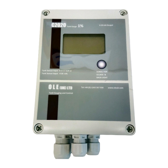
Page 10: Operation Instructions
Operation Instructions Overview Alarm Mute Button Scroll Button for Ullage and Backlight Audiable Alarm Calibration Switch Bund input Power Input 4-20mA Output – Loop / Passive Sensor Inputs See Page 4 Alarm Output Page 9 of 11... -
Page 11: Appendix 1 (C2020 Wiring Diagram)
Appendix 1 (C2020 Wiring Diagram) MAINS POWER SUPPLY Units are supplied with either 24vdc direct connection, or 100/240 Vac power supply. Power supply connections can Bund Alarm is an input for a be made by REMOVING the mechanical float switch Bund Alarm. -
Page 12: Appendix 2 (Accessories)
Appendix 2 (Accessories) B8 – Bund Probe / Level Switch The Bund Probe has an integral N/C (Normally Closed) level switch. The Sensor body is made from 304 Stainless Steel and the cap is 316 Stainless Steel. The float is NBR (Nitrile) which is good in Oil, Diesel, Petrol, most spirits and water based products (SG: 0.7 to 1.5).
Need help?
Do you have a question about the C2020 and is the answer not in the manual?
Questions and answers