Table of Contents
Advertisement
Quick Links
ChallengerOptics
Portable DWDM OTDR
CO-OTDR-DWDM
OPERATING MANUAL
Wavelength Specific Optical Testing and Measurement Equipment
CONTENTS
. . . . . . . . . . . . . . . . . . . . . . . . . . . . . . . . . . . . . . . . .
. . . . . . . . . . . . . . . . . . . . . . . . . . . . . . . . . . . . . . . . . . . . . . . . . . . .
. . . . . . . . . . . . . . . . . . . . . . . . . . . . . . . . . . . . . . . . .
Identification. . . . . . . . . . . . . . . . . . . . . . . . . . . . . . .
4.1
4.2
Identification and Configuration
. . . . . . . . . . . . . . . . . . . . . . . . . . . . . . . . . . . . . . . . .
5.1
5.2
5.3
5.4
Operations. . . . . . . . . . . . . . . . . . . . . . . . . . . . . . . . . . . . . . . . .
6.1
6.2
6.3
6.4
6.5
6.6
6.7
6.8
6.9
. . . . . . . . . . . . . . . . . . . . . . . . . . . . . . . . . . . . .
7.1
7.2
Management. . . . . . . . . . . . . . . . . . . . . . . . . . . . . . . . . . . . . . . . .
8.1
8.2
. . . . . . . . . . . . . . . . . . . . . . . . . . . . . . . . . . . . .
9.1
9.2
9.3
Locate. . . . . . . . . . . . . . . . . . . . . . . . . . . . . . . . . . . . . . . . . . . . . .
10.2 LTS Fault Locater Operation
11.0 Video
Scope. . . . . . . . . . . . . . . . . . . . . . . . . . . . . . . . . . . . . . . . . . . . . .
Locater. . . . . . . . . . . . . . . . . . . . . . . . . . . . . . . . . . . . . . .
. . . . . . . . . . . . . . . . . . . . . . . . . . . . . . . . . . . . . . . . . . . .
. . . . . . . . . . . . . . . . . . . . . . . . .
3
4
6
8
9
12
28
32
35
41
45
50
51
53
Advertisement
Table of Contents

Subscribe to Our Youtube Channel
Related Manuals for Challenger Optics CO-OTDR-DWDM

Summary of Contents for Challenger Optics CO-OTDR-DWDM
-
Page 1: Table Of Contents
......... CO-OTDR-DWDM 2.0 Safety... -
Page 2: Using This Manual
Chapter 1.0 - Using this Manual / 03 Chapter 2.0 - Safety / 04 This manual contains operation information for the Challenger Cable Sales CO-OTDR Optical Time Chapter 3 of this manual is a quick start guide. Prior to using the quick start guide or operating Domain Reflectometer. -
Page 3: Quick Start Guide
Chapter 2.0 - Safety / 05 Chapter 3.0 - Quick Start Guide / 06 CAUTION Press to turn on the OTDR. Fiber-optic connectors are easily contaminated or damaged. The connection to the This quick start guide demonstrates use by way of the touch screen unless the keypad is required. OTDR is physical contact type of connections and dirty or damaged connectors may impair the instruments capabilities at minimum and at worst result in the need to return Touch the OTDR icon located in the center of the Home screen. -
Page 4: Identification
Chapter 3.0 - Quick Start Guide / 07 Chapter 4.0 - Inspection / Identification / 08 4.1 Inspection Touch the (Range icon) to cycle through the available ranges of 500m, 1km, 4km, 16km, 64km, 128km or 256km. Before shipment, this instrument was inspected and found to be in perfect working order and Touch scan or press the Scan button to start a trace. -
Page 5: Otdr Description
Power Button 5.3 Power Requirements The CO-OTDR-DWDM is equipped with a 100-240V-0.4A input universal battery charger with 15V, 1.2A, (center positive output). The charger is supplied with interchangeable mains plugs for North America, Great Britain, Europe and Australia. The units internal power supply is an 11.1V 2600 mAh Li-ion battery. -
Page 6: Battery Replacement
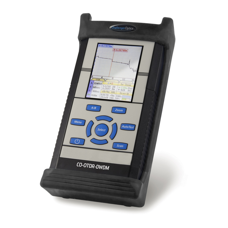
Chapter 5.0 - OTDR Description / 11 Chapter 6.0 - OTDR Operations / 12 5.4 Battery Replacement 6.1 Key Pad Batteries are factory installed. The unit should be returned to the factory for a new battery if Power button, turns the unit On and Off. A / B Zoom required. -
Page 7: Entering Otdr Function
Chapter 6.0 - OTDR Operations / 13 Chapter 6.0 - OTDR Operations / 14 6.2 Entering OTDR Function 6.4 Main OTDR Screen Press the power button the to turn on the OTDR. "A" Cursor with Position Data "B" Cursor with Position Data Use the LRUD buttons to highlight the OTDR icon and press the select button to enter Screen Tabs - Touching OTDR, Main Trace Screen... -
Page 8: Otdr Parameter Settings Screen
Chapter 6.0 - OTDR Operations / 15 Chapter 6.0 - OTDR Operations / 16 6.5 OTDR Parameter Settings Screen Trace Parameter Settings The cursor is the yellow highlighted area. (If the yellow cursor is on a value that is selected, that block will be highlighted green) The blue values are the currently selected values. -
Page 9: Auto Test
Chapter 6.0 - OTDR Operations / 17 Chapter 6.0 - OTDR Operations / 18 WARNING WARNING Before connecting a patch cord or fiber under test, be certain the fiber has no active Before connecting a patch cord or fiber under test, be certain the fiber has no active optical sources or instruments connected to the other end. -
Page 10: Trace Analysis
Chapter 6.0 - OTDR Operations / 19 Chapter 6.0 - OTDR Operations / 20 Pulse Width 6.8 Trace Analysis 10ns 30ns 100ns 300ns 1µ 3µ 10µ 20µ Unit of Measure The distance unit of measure may be either displayed in Kilometer (Km), Kilo feet (Kf ) or Miles 500m ü... -
Page 11: Loss Measurement Settings
Chapter 6.0 - OTDR Operations / 21 Chapter 6.0 - OTDR Operations / 22 Optical Return Loss Splice Loss Adjustment Areas This Optical Return Loss (ORL) is separate from the event ORL (Reflectance) that is displayed in the event analysis under the TYPE header for an individual event. The measurement displayed Basic Splice Loss LSA Splice Loss in the loss measurement area of the main OTDR screen and in the E (End of Fiber) row in the... -
Page 12: Event Analysis
Chapter 6.0 - OTDR Operations / 23 Chapter 6.0 - OTDR Operations / 24 LSA Examples 6.11 Event Analysis LSA Set Too Early: Enter Event Analysis The LSA area and cursor are set too early. To enter event analysis, press the menu button and use the left / right buttons to highlight the The right most green LSA indicator line Schematic View analysis icon and press select. - Page 13 Chapter 06 - OTDR Operations / 25 Chapter 06 - OTDR Operations / 26 Fib-R-Map The lowest setting possible should be used to help filter out any false events that may be caused by short pulse widths, but are not true perturbations in the optical signal. High sensitivity presents events with loss down to approximately 0.1dB, Medium (Md) with events down to approximately 0.2dB and Low (Lo) for event down to about 0.5dB.
-
Page 14: Project Management
Chapter 6.0 - OTDR Operations / 27 Chapter 7.0 - Project Management / 28 Table Definitions 7.1 Project Management Description # Event Number: Indicates the event in sequence, where the higher the number the further Project Management allows the user to save a set of parameters to be recalled for use at a later distance from the OTDR the event occurs. -
Page 15: Project Management Operation
Chapter 7.0 - Project Management / 29 Chapter 7.0 - Project Management / 30 Project Management File Tab 7.2 Project Management Operation To open the drop down menu under file, with file tab highlighted, press select or the down button. Use the down or up buttons to move through the drop down menu and select to Create a New Project choose and operation. -
Page 16: File Management
Chapter 7.0 - Project Management / 31 Chapter 8.0 - File Management / 32 Rename a Project 8.1 File management Description To rename a project, have the project to be renamed highlighted, press menu, to open the project management menu. Use the left and right buttons to highlight edit tab and press select File Management is use to save and recall traces. -
Page 17: File Management Operation
Chapter 8.0 - File Management / 33 Chapter 8.0 - File Management / 34 File Management File Tab Open/View a Trace To open the drop down menu under file, with file highlighted, press select or press the down To open a trace, press the menu button, highlight the file folder and press select. Use the up or button. -
Page 18: Tunable Laser Source
Chapter 9.0 - Tunable Laser Source / 35 Chapter 9.0 - Tunable Laser Source / 36 9.1 Laser Safety 9.2 TLS Quick Start Guide The Tunable Laser Source has been configured to provide laser radiation in the C Band of Prior to any operation please read the laser safety section of this chapter. -
Page 19: Operation
Chapter 9.0 - Tunable Laser Source / 37 Chapter 9.0 - Tunable Laser Source / 38 9.3 Operation Touch Screen Operation From the home screen, touch the TLS icon to enter the tunable laser source feature. Laser Start/Stop/Activity Indicator Flashing indicates active laser Starts and stops laser/sweep TLS Screen Description Home Icon Brings the user back to the home page... - Page 20 Chapter 9.0 - Tunable Laser Source / 39 Chapter 9.0 - Tunable Laser Source / 40 Setting Parameters Manual/CW Operation To fire the laser in a CW mode, Set the output to the desired unit, set the step size if required and Set Output Units set the power lever to dBm level required.
-
Page 21: Fault Locate
Chapter 10.0 - Fault Locate / 41 Chapter 10.0 - Fault Locate / 42 10.1 Fault Locater Description Fib-R-Map The Fault Locater is a simple auto test feature which displays the test results in event table with the Fib-R-Map schematic view. The fault locater will take a scan of the fiber in auto test mode. Range of the Trace The user sets the wavelength to be tested and the OTDR will set the pulse width and range to best suite the fiber under test at the selected wavelength. - Page 22 Chapter 10.0 - Fault Locate / 43 Chapter 10.0 - Fault Locate / 44 Event Table Definitions 10.2 Fault Locater Operation # Event Number: Set Wavelength Indicates the event in sequence, where the higher the number the further distance from the To set the wavelength first enter the OTDR mode and touch the Lambda icon or wavelength to OTDR the event occurs.
-
Page 23: Entering Video Scope Function
Chapter 11.0 - Video Scope / 45 Chapter 11.0 - Video Scope / 46 11.1 Entering Video Scope Function Quick Save Press the menu button, use the left or right buttons to highlight the quick save icon and press the select button to store a file image of the scope screen in the file folder within an active project. -
Page 24: Video Scope Operation
Chapter 11.0 - Video Scope / 47 Chapter 11.0 - Video Scope / 48 Brightness Centering a Connector Image Press the menu button, use the left and right buttons to highlight the brightness icon, use the Once the image is stable and focused, use the stylus to touch the approximate center of the Select button to cycle through the adjustments for the brightness level. -
Page 25: Pass/Fail Criteria Tables
Chapter 11.0 - Video Scope / 49 Chapter 12.0 - Visual Fault Locater / 50 11.6 Pass/Fail Criteria Tables 12.1 VFL Safety Fiber End Face Criteria Table for Angled PC Polished Connectors Zone Description Diameter Allowable Scratches (W) Allowable Defects (D) Critical Zone 0µm to 25µm ≤... -
Page 26: Specifications
Chapter 13.0 - Specifications / 51 Chapter 13.0 - Specifications / 52 CAUTION Laser Safety Never look directly into the end of a connected fiber optic cable or fiber optic interface of optical test equipment, to do so could expose the user to laser radiation and could result in VISIBLE FAULT LOCATER personal injury. -
Page 27: Repair/Warranty/ Version Control
Chapter 14.0 - Repair/Warranty/ Version Control / 53 14.1 Repair Information If repair is required, simply call the factory at 1-310-338-9971 for return instructions and a RMA number. 14.2 Warranty Information This product, including all mechanical, electrical, and optical parts and assemblies are unconditionally warranted to be free of defects in workmanship and material for a period of one (1) year from the date of delivery.
Need help?
Do you have a question about the CO-OTDR-DWDM and is the answer not in the manual?
Questions and answers