Advertisement
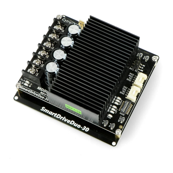
SmartDriveDuo-30
MDDS30
User's Manual
Rev 1.0
April 2017
Information contained in this publication regarding device applications and the like is intended through
suggestion only and may be superseded by updates. It is your responsibility to ensure that your application
meets with your specifications. No representation or warranty is given and no liability is assumed by Cytron
Technologies Incorporated with respect to the accuracy or use of such information or infringement of
patents or other intellectual property rights arising from such use or otherwise. Use of Cytron
Technologies's products as critical components in life support system is not authorized except with express
written approval by Cytron Technologies. No licenses are conveyed, implicitly or otherwise, under any
intellectual property rights.
Advertisement

Subscribe to Our Youtube Channel
Related Manuals for Cytron SmartDriveDuo-30


Summary of Contents for Cytron SmartDriveDuo-30
- Page 1 It is your responsibility to ensure that your application meets with your specifications. No representation or warranty is given and no liability is assumed by Cytron Technologies Incorporated with respect to the accuracy or use of such information or infringement of patents or other intellectual property rights arising from such use or otherwise.
-
Page 2: Table Of Contents
ROBOT.HEAD to TOE M DDS30 Product User’s Manual - INDEX PAGES 2 INTRODUCTION 3 PACKING LIST 4 PRODUCT SPECIFICATIONS 6 BOARD LAYOUT 8 POWER SUPPLY 9 MOTOR CONNECTION 10 SAFETY FEATURES 11 INPUT MODES 13 8.1. RC (Radio Control) 15 ... -
Page 3: Introduction
Product User’s Manual - 1. INTRODUCTION SmartDriveDuo-30 is one of the latest smart series motor drivers designed to drive medium power brushed DC motor with current capacity up to 80A peak (few seconds) and 30A continuously, each channel. This driver is designed specially for controlling differential drive mobile robot using RC controller. -
Page 4: Packing List
immediately. s ales@cytron.com.my ITEMS QUANTITY SmartDriveDuo-30 (Code: M DDS30 ) W R-EX-GROVE Grove 4 Pin Buckled 20cm Cable (Code: W R-EX-2561-03 2561 3 Ways Connector Extension Wire (Code: Optional External Fan (Not included):... -
Page 5: Product Specifications
ROBOT.HEAD to TOE M DDS30 Product User’s Manual - 3. PRODUCT SPECIFICATIONS Dimension (unit in mm): ● MDDS30 main board. ● MDDS30 height. Created by C ytron Technologies Sdn Bhd – All Rights Reserved Back to I NDEX... - Page 6 ROBOT.HEAD to TOE M DDS30 Product User’s Manual - MDDS30 bottom cover: Absolute Maximum Rating of SmartDriveDuo-30: PARAMETERS Unit Input Voltage (Motor Supply Voltage) – I (Max Continuous Motor Current) – – MAX I (Peak Motor Current) – –...
-
Page 7: Board Layout
ROBOT.HEAD to TOE M DDS30 Product User’s Manual - 4. BOARD LAYOUT LABEL FUNCTION MOTOR RIGHT LED INDICATOR A Indication for current flow and direction for motor RIGHT. If LED MRA turns on, means current flows from output MRA to MRB. Vice versa. MOTOR RIGHT TERMINAL BLOCK B ... - Page 8 ROBOT.HEAD to TOE M DDS30 Product User’s Manual - G HEAT SINK This area might be hot, please be careful. RIGHT CHANNEL LED INDICATOR RUN - T urns on when motor RIGHT is running. If signal error received for motor RIGHT, it will H ...
-
Page 9: Power Supply
● 7V – 35V power supply. M UST BE IN PARALLEL WITH A BATTERY WITH SAME VOLTAGE The power source can be connected to SmartDriveDuo-30 either via the terminal block, or soldered directly to the pad at the bottom layer. ... -
Page 10: Motor Connection
ROBOT.HEAD to TOE M DDS30 Product User’s Manual - 6. MOTOR CONNECTION Similar to the power supply, connection to the motor can be made either via the terminal block, or it can be soldered directly to the bottom layer pad. For MIXED mode, especially for ... -
Page 11: Safety Features
2 times) 1. Input Error ( E rror LED Every time SmartDriveDuo-30 is power up, the input data must be ‘stop’ (for RC, Analog, PWM input mode). This feature prevent the driver from sudden run, especially when the driver accidently reset. -
Page 12: Input Modes
Product User’s Manual - 8. INPUT MODES When the SmartDriveDuo-30 is powered up, RUN (Left), ERR (Left), RUN (Right) and ERR (Right) LEDs will running once. After that, the input mode will be read from the DIP switch and retained as long as the driver is powered. If you wish to change the input mode, you will need to change the setting on the DIP switch and press the RESET button, or power cycle the driver (turn it off and turn it on again). - Page 13 NOTE The RC transmitter must be ON before power up the SmartDriveDuo-30. RC Input mode is selected by setting the SW1 & SW2 to 0 (Down). SW3 – SW6 can be configured depending on the requirement of the user.
- Page 14 This is useful when a microcontroller is used to control the motor. The microcontroller does not need to send the pulse continuously to the SmartDriveDuo-30. Instead, it only needs to send a single pulse when the speed or direction of the motor needs to be changed.
- Page 15 ROBOT.HEAD to TOE M DDS30 Product User’s Manual - ● RC Mode with microcontroller (Independent Both) ON 1 2 3 4 5 6 7 8 *Sample connection for MDDS30 with (or ...
- Page 16 PWM, it can accept TTL PWM from 1.3 to 5V for HIGH level (refer to P roduct Specifications NOTE The Analog/PWM signal to stop the motor must be available when SmartDriveDuo-30 is turned on/reset. Else, the driver will show Input Error until the correct (stop) signal is available.
- Page 17 ROBOT.HEAD to TOE M DDS30 Product User’s Manual - 1 The response to input is exponential and thus soften the control around the center zero speed point. This is suitable for high speed and very sensitive motor. 0 LOCKED ANTI-PHASE Motor stops when the input signal is 2.5V.
- Page 18 Product User’s Manual - 8.3 Serial Simplified In Serial Simplified mode, SmartDriveDuo-30 is controlled by using the UART interface. IN1 pin is connected to the UART receive pin. IN2, AN1 and AN2 pins are not used in this mode.
- Page 19 ROBOT.HEAD to TOE M DDS30 Product User’s Manual - Example Serial Simplified data: Binary bits Decimal 0 0 0 0 0 0 0 0 0 motor LEFT stop. 0 0 1 1 1 1 1 1 63 motor LEFT full speed CW. 0 ...
- Page 20 When the driver is powered up and waiting for the header byte, the error LED will blink and indicate that there is input error. SmartDriveDuo-30 may take up to 500ms to start up after power is applied. Sending a dummy byte for auto-baudrate during this period may cause undesirable results. Please allow one-second delay between applying power and sending a dummy byte.
- Page 21 ROBOT.HEAD to TOE M DDS30 Product User’s Manual - A packet consists of 4 bytes and the format is shown in the following table. VALUE BYTE NAME DESCRIPTION (Decimal) Header To indicate the start of packet. Used to identify the driver when multiple units are Channel...
- Page 22 ● Warranty only applies to manufacturing defect. ● Damaged caused by misuse is not covered under warranty. ● Warranty does not cover freight cost for both ways. Prepared by: Cytron Technologies Sdn Bhd www.cytron.com.my No. 1, Lorong Industri Impian 1, Taman Industri Impian, 14000 Bukit Mertajam, Penang, Malaysia.
Need help?
Do you have a question about the SmartDriveDuo-30 and is the answer not in the manual?
Questions and answers