Table of Contents
Advertisement
Quick Links
Advertisement
Table of Contents

Related Manuals for EEVBlog 121GW


Summary of Contents for EEVBlog 121GW
- Page 1 121GW Multimeter User’s Manual Last Revised 26 October 2018...
-
Page 2: Table Of Contents
Frequency & Duty Cycle ..................16 VA ..........................16 Temperature & Continuity .................16 Bluetooth ......................17 Standards ....................18 Compliance Symbols..................18 IEC Standards ..................... 18 ANSI Standards ....................18 Safety (EN) ..................19 Sécurité (FR) ..................21 121GW Multimeter User’s Manual 26 Oct 2018... - Page 3 DC μA & AC μA ....................40 Burden Voltage ....................41 Low Burden Feature ..................41 A practical example of measuring current ..........43 Power (VA) ......................44 Connections overview ..................44 DC & AC mVA/VA ...................45 DC µVA & AC μVA...................46 121GW Multimeter User’s Manual 26 Oct 2018...
- Page 4 MIN / MAX / AVG ....................57 Backlight .....................58 Data Logging ..................59 Bluetooth .....................60 Setup Menu ..................61 Maintenance ..................64 Debugging......................64 Cleaning & Storage ..................... 64 Fuse Replacement ................65 Calibration ...................66 Firmware Update .................70 Warranty ....................71 121GW Multimeter User’s Manual 26 Oct 2018...
- Page 5 Figure 22 Measuring on the resistance range ........... 48 Figure 23 Measuring on the continuity range ............ 49 Figure 24 Measuring on the capacitance range ..........52 Figure 25 Measuring on the frequency range ............ 53 121GW Multimeter User’s Manual 26 Oct 2018...
- Page 6 121GW Multimeter User’s Manual 26 Oct 2018...
-
Page 7: Contact
This multimeter and its accessories can be purchased from the online store at: www.eevblog.com Community support for this meter is provided on the EEVBlog Forum at: www.eevblog.com/forum If you have an urgent request, or cannot get the help you need online, you can call us on: +61(2) 8626 8743. -
Page 8: Glossary Of Terms
The voltage that a function of the Multimeter than withstand. Accuracy The closeness of a measured value to a known standard. Low Burden Provides low burden voltage when measuring current compared with typical multimeters, minimising impact on your in-circuit current measurements. 121GW Multimeter User’s Manual 26 Oct 2018... -
Page 9: Change Log
• New style and graphics • Added Serial Number section • Added Hold requirement to save setup items 15th January 2018 • Fixed various grammar errors • Added Bluetooth symbol to frontpage 11th December 2017 Original Release 121GW Multimeter User’s Manual 26 Oct 2018... -
Page 10: General
• Connect the equipment into an outlet on a circuit different from that to which the receiver is connected. • Consult the dealer or an experienced radio/TV technician for help. WARNING Any changes or modifications not expressly approved by the manufacturer could void the user’s authority to operate the equipment. 121GW Multimeter User’s Manual 26 Oct 2018... -
Page 11: Introduction
Introduction Congratulations on purchasing the EEVBlog 121GW Multimeter. It’s one of the most feature packed small form factor meters on the market, designed to provide maximum functionality in as little bench space as possible. It has many unique features not found on other multimeters, like low burden voltage measurement and display, simultaneous voltage and current (VA power) measurement, 15V diode test voltage, Bluetooth built-in, and Micro SD card data logging. -
Page 12: Multimeter Features
• Android and Windows 10 support (iPhone, Mac, Windows Phone • Updatable Firmware (via Micro SD Card) Batteries • RTC Battery - 1 x CR1220 • Main Batteries - 4 x AA for long life of >500 hours Under Development 121GW Multimeter User’s Manual 26 Oct 2018... -
Page 13: Specifications
IR 20 kA HRC fast + diode V & Auto V 600 V DC/AC RMS PTC & MOV protection mV, ohm & others 600 V DC/AC RMS PTC & MOV protection Low battery voltage Below approx. 4.2 V 121GW Multimeter User’s Manual 26 Oct 2018... -
Page 14: Dc & Ac Voltage
The AC Bandwidth extends beyond 5 kHz, but the meter is only specified and calibrated at 5 kHz. The AD8436 used specifies an additional 1% error up to 65 kHz. Higher frequency is possible with additional error above that again. 121GW Multimeter User’s Manual 26 Oct 2018... -
Page 15: Current
7 mA short circuit This channel has overload protection for up to 600 V. A nominal 2.2 K resistor (includes PTC) is in series with the voltage source and is what limits the test current. 121GW Multimeter User’s Manual 26 Oct 2018... -
Page 16: Frequency & Duty Cycle
Internal temperature measurement is inside a sealed case, so will have some thermal lag. The continuity tester can be set for beep on CLOSED or beep on OPEN (for wire breaks) with a user adjustable threshold level. 121GW Multimeter User’s Manual 26 Oct 2018... -
Page 17: Bluetooth
Bluetooth • The 121GW uses a BLE112-A Class 2 certified Low Energy Bluetooth module. • This device complies with Part 15 of the FCC Rules. • This device complies with Industry Canada licence-exempt RSS standard(s). • This device complies with Japan MIC certification ARIB STD-T66. -
Page 18: Standards
Tested for IEC 60950-1 and IEC/EN61010-1: 2010 3rd Edition. ANSI Standards Safety requirements tested as per ANSI 61010-1 and testing for hand-held equipment as per ANSI 61010-2. CAT III rating as per ANSI 61010-1. 121GW Multimeter User’s Manual 26 Oct 2018... -
Page 19: Safety (En)
5. CAT III & CAT IV test probe tips must be 4 mm (as per IEC 61010-031). 6. All accessories must possess a greater than or equal to CAT rating to that of the multimeter. 121GW Multimeter User’s Manual 26 Oct 2018... - Page 20 1. Before changing functions, remove test leads from any measurement point. 2. Before any measurement, ensure test leads are connected to appropriate connector on the device and in an appropriate manner to the test points. 121GW Multimeter User’s Manual 26 Oct 2018...
-
Page 21: Sécurité (Fr)
5. Les pointes de la sonde de test CAT III et VAT IV doivent être de 4 mm (selon CEI 61010-031). 6. Tous les accessoires doivent posséder une valeur nominale supérieure ou égale à celle du multimètre. 121GW Multimeter User’s Manual 26 Oct 2018... - Page 22 1. Avant de modifier les fonctions, retirez les fils de test de n'importe quel point de mesure. 2. Avant toute mesure, assurez-vous que les fils de test sont connectés au connecteur approprié sur l'appareil et de manière appropriée aux points de test. 121GW Multimeter User’s Manual 26 Oct 2018...
-
Page 23: Symbols
Meaning Symbol Meaning Dangerous Voltage Warning or Caution AC - Alternating Current Ground DC - Direct Current Double Insulation (Protection Class II) Either AC or DC Fuse Not Applicable to Identified Model Battery 121GW Multimeter User’s Manual 26 Oct 2018... -
Page 24: Meter Overview
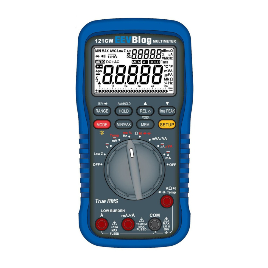
Low Z Ω Temp True RMS LOW BURDEN 500mA mA A 400mA CAT III 600V FUSED FUSED Figure 1 Front panel Legend Number Item Name See Page Display screen Keypad Rotary switch Input terminals 121GW Multimeter User’s Manual 26 Oct 2018... -
Page 25: Back
Back The diagram below labels important features on the back of your meter. Magnetic clip holder Probe holders Rubber boot Tilting bail Figure 2 Back view 121GW Multimeter User’s Manual 26 Oct 2018... -
Page 26: Display Screen
Used to turn the power on and off and to select the primary measurement function. There are two (2) OFF positions for convenience, and both work identically. Temp Ω mVA/VA Low Z Figure 4 Rotary switch 121GW Multimeter User’s Manual 26 Oct 2018... -
Page 27: Keypad
• Pressing once allows viewing of the stored data. PEAK 1kHz • Displays the setup menu and cycles through the meter's options. SETUP • Press and hold the button when on the required option to edit that option. 121GW Multimeter User’s Manual 26 Oct 2018... -
Page 28: Input Terminals
The common jack (ground / negative) for all ranges and functions. Volts Ω Ohms • The positive input jack used for voltage, resistance, capacitance, Temp Continuity diode, continuity, and temperature functions. Capacitance • This input jack is PTC and MOV protected. Diode Temperature 121GW Multimeter User’s Manual 26 Oct 2018... -
Page 29: Mva/Va Va
0 . 0 00 Temperature Temp ms % Low Z AC mV 0 . 0 00 0 . 0 0 mVA/VA Ω Temperature 0FL . Temperature Temp mVA/VA ms % Ω Low Z mVA/VA Ω 121GW Multimeter User’s Manual 26 Oct 2018... -
Page 30: Offv
0 . 0 000 DC mVA/VA 0 . 0 mVA/VA Temp Ω ms % 0 . 0 0 Low Z 0 . 0 000 0 . 0 AC mVA/VA mVA/VA Ω 0 . 0 0 121GW Multimeter User’s Manual 26 Oct 2018... - Page 31 Symbol Display Display Display Temp ms % Low Z DC A/mA 0 . 0 0 bd . 0 FF mVA/VA Ω AC A/mA 0 . 0 0 bd . 0 FF mVA/VA Ω 121GW Multimeter User’s Manual 26 Oct 2018...
-
Page 32: Ms % Mv
Figure 5 Measuring on the DC V range This switch position has two further ranges, AC volts and DC + AC volts. See the table on page 29 for a list of these modes. 121GW Multimeter User’s Manual 26 Oct 2018... -
Page 33: Ac Voltage
Figure 6 Measuring on the AC V range This switch position has two further ranges, DC volts and DC + AC volts. See the table on page XX for a list of these modes. 121GW Multimeter User’s Manual 26 Oct 2018... -
Page 34: Dbm Measurement
The value of dBm is defined and calculated as follows (note that R is by convention): P = 10 log = 600 = 1 mW Ω dBm = 10 log = 10log 0.001 Figure 8 dBm measurement calculation 121GW Multimeter User’s Manual 26 Oct 2018... -
Page 35: Dc + Ac Volts
Figure 9 Measuring on the DC + AC V range This switch position has two further ranges, DC volts and AC volts. See the table on page XX for a list of these modes. 121GW Multimeter User’s Manual 26 Oct 2018... -
Page 36: Dc Mv & Ac Mv
CAT III 600V FUSED FUSED Figure 10 Measuring on the DC mV range This switch position has Temperature as a third mode. See the table on page XX for a list of these modes. 121GW Multimeter User’s Manual 26 Oct 2018... -
Page 37: Low Z Dc Voltage
Connect the probes to the input terminals as shown below in Figure DC volts is measured between the two probes. Figure 11 Measuring on the Low Z range 121GW Multimeter User’s Manual 26 Oct 2018... -
Page 38: Current
600V FUSED FUSED Figure 12 Measuring on the DC A/mA range To further clarify how your leads should be connected for measuring current, please see page XX which shows a practical, real-world example. 121GW Multimeter User’s Manual 26 Oct 2018... -
Page 39: Ac Amps / Ac Milliamps
Figure 13 Measuring on the AC A/mA range This switch position has one other range, DC A/mA. See the table on page XX for a list of these modes. 121GW Multimeter User’s Manual 26 Oct 2018... -
Page 40: Dc Μa & Ac Μa
FUSED Figure 14 Measuring on the μA (microamps) range This switch position has two other modes, DC µVA and AC µVA. See the table on page XX for a list of these modes. 121GW Multimeter User’s Manual 26 Oct 2018... -
Page 41: Burden Voltage
Low Burden Feature Your 121GW Multimeter comes with a unique Low Burden measurement feature. Not only does the multimeter show you the burden voltage when measuring current, something that very few multimeters can do, it is also designed to make the burden voltage as small as possible. -
Page 42: Figure 15 Lead Configuration For Measuring Burden Voltage On The A / Ma Mode
Ω mVA/VA Low Z mVA/VA Ω Ω Temp True RMS LOW BURDEN 500mA mA A 400mA CAT III 600V FUSED FUSED Figure 16 Lead configuration for measuring burden voltage on the μA range 121GW Multimeter User’s Manual 26 Oct 2018... -
Page 43: A Practical Example Of Measuring Current
Low Z mVA/VA Ω Ω Temp True RMS LOW BURDEN 500mA mA A Load 400mA CAT III 600V FUSED FUSED Figure 17 Practical example of how to connect leads when measuring current 121GW Multimeter User’s Manual 26 Oct 2018... -
Page 44: Power (Va)
Be careful to connect the system in a manner that the meter's common terminal is common for both the voltage and current measurement. Battery Device Circuit Meter Figure 18 The correct electrical connections for making measurements on power (VA) modes 121GW Multimeter User’s Manual 26 Oct 2018... -
Page 45: Dc & Ac Mva/Va
AC mVA/VA then the meter will remember your choice, so you may have to select the 1kHz mode again by pressing MODE MIN/MAX SETUP Figure 19 Meter terminals to use when measuring on the DC & AC mVA/VA mode 121GW Multimeter User’s Manual 26 Oct 2018... -
Page 46: Dc Μva & Ac Μva
1kHz pressing MODE MIN/MAX SETUP Figure 20 Meter terminals to use when measuring on the DC µVA & AC µVA modes 121GW Multimeter User’s Manual 26 Oct 2018... -
Page 47: Temperature
MIN/MAX SETUP Figure 21 Measuring in the temperature mode This switch position has two other modes, DC mV and AC mV. See the table on page XX for a list of these modes. 121GW Multimeter User’s Manual 26 Oct 2018... -
Page 48: Resistance
FUSED FUSED Figure 22 Measuring on the resistance range This switch position has three other modes, continuity/cable break, diodes and capacitance. See the table on page XX for a list of these modes. 121GW Multimeter User’s Manual 26 Oct 2018... -
Page 49: Continuity & Cable Break
These are listed in the table below. Test Type Setting Threshold Continuity >30 Ω This is the default setting dm 30 Cable break >30 Ω UP 30 Continuity >300 Ω dm 300 Cable break >300 Ω UP 300 121GW Multimeter User’s Manual 26 Oct 2018... - Page 50 (and/or the meter beeps). You have now changed the setting. This switch position has three other modes, resistance, diodes and capacitance. See the table on page XX for a list of these modes. 121GW Multimeter User’s Manual 26 Oct 2018...
-
Page 51: Diodes
Diodes 121GW Multimeter User’s Manual 26 Oct 2018... -
Page 52: Capacitance
FUSED FUSED Figure 24 Measuring on the capacitance range This switch position has three other modes, resistance, continuity/cable break and diodes. See the table on page XX for a list of these modes. 121GW Multimeter User’s Manual 26 Oct 2018... -
Page 53: Frequency
600V FUSED FUSED Figure 25 Measuring on the frequency range This switch position has two other modes, period and duty cycle. See the table on page XX for a list of these modes. 121GW Multimeter User’s Manual 26 Oct 2018... -
Page 54: Period
Period 121GW Multimeter User’s Manual 26 Oct 2018... -
Page 55: Duty Cycle
Duty Cycle 121GW Multimeter User’s Manual 26 Oct 2018... -
Page 56: Other Measurement Functions
All subsequent measurements will have this stored relative value subtracted from the result. The displayed measurement is the difference between the actual measured value and the stored relative value. If is useful for example to cancel out the resistance of test probes in the ohms range. 121GW Multimeter User’s Manual 26 Oct 2018... -
Page 57: Min / Max / Avg
To exit out of these modes hold the button until a beep is heard, and the icons are cleared from the screen. Pressing the MIN/MAX button will cycle through the displayed results of each measurement. 121GW Multimeter User’s Manual 26 Oct 2018... -
Page 58: Backlight
Backlight To enable the backlight, hold the MODE button. 121GW Multimeter User’s Manual 26 Oct 2018... -
Page 59: Data Logging
The data that is recorded is taken from the currently displayed function, if you are measuring voltage then voltage is recorded. The number of accumu- lated logged data points is displayed on the secondary display. To stop data logging press and hold the MEM button. 121GW Multimeter User’s Manual 26 Oct 2018... -
Page 60: Bluetooth
The multimeter will continue to functional as normal in Bluetooth mode, but the display data will be transmitted via the Bluetooth connection. To disable Bluetooth mode press and hold the 1ms Peak button until BT is not displayed. 121GW Multimeter User’s Manual 26 Oct 2018... -
Page 61: Setup Menu
The Low Battery icon will come in when the batteries reach approximately 4.2 V It is recommended that you change the battery when the battery icon is dis- played, as the unit’s specifications are no longer guaranteed. AUTO POWER OFF (APO) 121GW Multimeter User’s Manual 26 Oct 2018... - Page 62 There are three menu items that can be used to read and set the currently configured date. These are the following menu items: 1. Year “YYYY” 2. Month-Day “MM-DD” 3. Hour-Minute “HH-mm” To change the date items: 121GW Multimeter User’s Manual 26 Oct 2018...
- Page 63 MULTIMETER ID This is a user configurable ID which is used to differentiate between multiple 121GW units. The value is what appears in the App and is can be changed by doing the following: 1. Navigate to the menu item “XXXXX” using SETUP (Where X are num- bers) 2.
-
Page 64: Maintenance
Maintenance The 121GW maintenance is outlined in this section. Before opening case for maintenance, disconnect test leads from the meter and turn off the meter. Debugging 1. If a low battery alert appears on the device as indicated in the opera- tion section, the back of the device must be opened to replace the AA batteries. -
Page 65: Fuse Replacement
Recommended: ASTM HV610.0.4 400 mA (600V) or HV620.0.4 (1000V) A/500 mA current input fuse: 11 A/1000 V DC/AC, IR 20 kA HRC FAST Dimension: 10mm x 38 mm 5AG Recommended: ASTM HV110.11A, Bussmann DMM-B-11A, or Littlefuse FLU011 121GW Multimeter User’s Manual 26 Oct 2018... -
Page 66: Calibration
NOTE: Calibration should be performed in this order: 1. Offset calibration 2. Scale calibration SAVING CALIBRATION DATA To backup calibration data you can perform the following procedure: 1. Ensure an SD card is in the multimeter. 121GW Multimeter User’s Manual 26 Oct 2018... - Page 67 1. Follow the steps shown in the section “Cal- ibration Mode”. 2. Disconnect or short the input that would result in a zero reading as required for that function: Mode Action Low Z Open Circuit Voltage DC/AC Short Inputs Capacitance Open Circuit 121GW Multimeter User’s Manual 26 Oct 2018...
- Page 68 Beard stroking is allowed. 4. Press the MEM button to begin gain calibration. 5. There will be a timer countdown. When the timer reaches zero the gain calibration will complete and will be stored. 121GW Multimeter User’s Manual 26 Oct 2018...
- Page 69 NOTE: If you do not setup the leads prior to starting the offset calibration then the final calibration value will be affected. If at any time during the timer countdown the measurement is interrupted the offset calibration pro- cedure should be restarted. 121GW Multimeter User’s Manual 26 Oct 2018...
-
Page 70: Firmware Update
Firmware Update The 121GW features updatable firmware that enables upgrades to be per- formed by the user from the SD card. To perform a firmware update, follow the following procedure: 1. Turn off the multimeter. 2. Insert an SD card into the multimeter with the latest EEVblog.bin firmware file. -
Page 71: Warranty
Warranty The 121GW is warranted to be free from defects in materials and workman- ship for a period of one year from the date of purchase. If within the war- ranty period your instrument should become inoperative from such defects, the unit will be repaired or replaced at the company’s option. - Page 72 121GW Multimeter User’s Manual 26 Oct 2018...
- Page 73 121GW Multimeter User’s Manual 26 Oct 2018...
- Page 74 121GW Multimeter User’s Manual 26 Oct 2018...
- Page 75 121GW Multimeter User’s Manual 26 Oct 2018...
- Page 76 121GW Multimeter User’s Manual 26 Oct 2018...
Need help?
Do you have a question about the 121GW and is the answer not in the manual?
Questions and answers