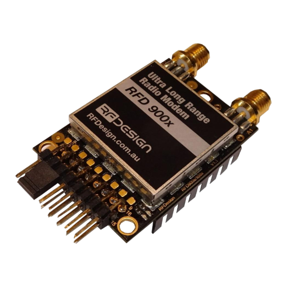
Summary of Contents for RFDesign RFD900 Series
- Page 1 RFD900x Multipoint firmware User Manual Configuration and usage guide Flash Programmer User Manual Last update 06/12/2016...
-
Page 2: Table Of Contents
RFD900x Data Sheet www.rfdesign.com.au RFDesign Pty Ltd 7/1 Stockwell Place Archerfield, QLD 4108 rfdesign.com.au Table of contents Table of contents ............................ 1 Introduction ............................ 2 Software/GCS Support ........................3 AT commands..........................4 Setting up data encryption ..................... 8 Setting the air data rate ......................8 Multipoint Network ........................ -
Page 3: Introduction
RFD900x Data Sheet www.rfdesign.com.au 1 Introduction The RFD900x radio modem can be loaded with three official firmware releases to achieve different communication architectures and node topologies. So far, the available firmware versions are: • Peer-to-peer (P2P) • Multipoint network •... -
Page 4: Software/Gcs Support
RFD900x Data Sheet www.rfdesign.com.au 2 Software/GCS Support The Multipoint network firmware is currently only configurable using AT Commands support for managing settings using the RFD tools may be added later. Default serial port settings are as follows: • 57600 baud rate •... -
Page 5: At Commands
RFD900x Data Sheet www.rfdesign.com.au 3 AT commands The RFD900x modem can support the Hayes ‘AT’ modem command set for configuration. The AT command mode can be entered by using the ‘+++’ sequence in a serial terminal connected to the radio. When doing this, you must allow at least 1 second after any data is sent to be ensure the request for command mode is not interpreted as data. - Page 6 RFD900x Data Sheet www.rfdesign.com.au ATPR=X Shows GPIO input state ATPC=X,S Sets output GPIO X to state S AT&M? Current master node settings AT&MX=A,B Describes the network configuration. Only set this on master node(NETID=0, NODEID=1). X is the network number (note must start with 0 as this is the synchronising network).
- Page 7 RFD900x Data Sheet www.rfdesign.com.au Issuing a RT, command will take effect only in the remote node in a peer-to-peer configuration, which if a very useful feature if you have a remote node that is hard to access. Just make sure to keep the parameters compatible, whenever changing a parameter in the remote node.
- Page 8 RFD900x Data Sheet www.rfdesign.com.au MIN_FREQ 915000 927000 902000 Min frequency in KHz MAX_FREQ 928000 928000 903000 Max frequency in KHz S10 NUM_CHANNELS Number of frequency hopping channels. Do not change as this will affect the spectrum separation of the nodes...
-
Page 9: Setting Up Data Encryption
RFD900x Data Sheet www.rfdesign.com.au Notes: To ensure the correct channel separation between networks this should only take the values 0,7 or 13 ECC - Software Detection and correction, extra packet information, twice the packet length, is sent to allow the recovery of corrupted packets. -
Page 10: Multipoint Network
RFD900x Data Sheet www.rfdesign.com.au 4 Multipoint Network The multipoint mode requires the firmware to be loaded into the all network radios. Check section “Useful links” for the download link and refer to section “RFD900x Flash Programmer tool” to flash the multipoint firmware. After flashing the device, you are required to choose a master node that will control the radio timeslot allocations. - Page 11 RFD900x Data Sheet www.rfdesign.com.au 64kbps Airspeed Networks Single network (Maximum 3 non-master nodes) Parrameter Value 915000 928000 y*** 1**** * Dependent on range and power requirements. Lower power generally lowers range. ** For sending mavlink data *** Depends on the network structure. Master node (1) must be set to broadcast (255). Most commonly nodes will address the master (1) **** Master node only.
- Page 12 RFD900x Data Sheet www.rfdesign.com.au GCS → Vehicle1 2 ->3 (When in range) Vehicle2 → GCS 4 → 2 GCS → Vehicle2 2 → 4 Settings as for single network with the following exceptions NodeID 1 (aka Relay) Parrameter Value NodeID 2 (aka GCS)
- Page 13 RFD900x Data Sheet www.rfdesign.com.au 1**** * Dependent on range and power requirements. Lower power generally lowers range. ** For sending mavlink data *** Depends on the network structure. Master node (1) must be set to broadcast (255). Most commonly nodes will address the master (1) **** Master node only.
-
Page 14: Frequently Asked Questions (Faq)
RFD900x Data Sheet www.rfdesign.com.au 5 Frequently asked questions (FAQ) How many antennas do I need to use? One is the minimum. Two is recommended. How do I connect the FTDI cable to the modem? The black cable of the FTDI (pin 1) should connect to pin 1 on the modem as shown in Figure 13-1. -
Page 15: Useful Links
RFD900x Data Sheet www.rfdesign.com.au 6 Useful links RFD900x Firmware http://rfdesign.com.au/firmware/ RFD SiK firmware is standard SiK (open source) RFD Multipoint firmware is multipoint SiK (MP SiK) RFD900x Flash Programmer http://rfdesign.com.au/downloads/ FTDI Cable documentation http://www.ftdichip.com/Support/Documents/DataSheets/Cables/DS_TTL-232R_CABLES.pdf Last update 06/12/2016... -
Page 16: Document Revision History
RFD900x Data Sheet www.rfdesign.com.au 1 Document revision history Version Date Changes 20/08/18 Release document Last update 06/12/2016...


Need help?
Do you have a question about the RFD900 Series and is the answer not in the manual?
Questions and answers