Table of Contents
Advertisement
Quick Links
Advertisement
Table of Contents

Summary of Contents for Manitowoc Multiplex 42MA04
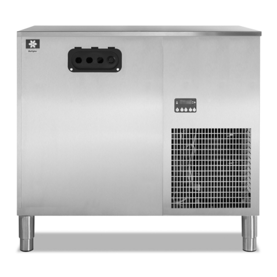
- Page 1 Post Mix Soda and Super-Chil™ Refrigeration Unit with Electronic Control Installation, Operation and Maintenance Manual This manual is updated as new information and models are released. Visit our website fo rthe latest manual. www.manitowocbeverage.com/us Part Number 020002365 08/25/2015...
- Page 2 It contains valuable care and maintenance safety notices: information. If you encounter problems not covered by this manual, do not proceed, contact Manitowoc Warning Beverage Equipment. We will be happy to provide Text in a Warning box alerts you to a potential personal assistance.
-
Page 3: Table Of Contents
Table of Contents Section 1 General Information Read This Manual ....................... 5 Unit Inspection ........................5 Model Numbers ........................5 How to Read a Model Number ..................5 Accessories .......................... 6 Special Applications ......................6 Attention: Marine Installations ......................6 Outdoor Applications ...........................6 Serial Plate Location ...................... - Page 4 Table of Contents (continued) Connecting Insulated Supply Lines ....................25 Insulating Connections ........................27 Aeroquip Connection .......................27 Condenser and Pre-charged Lines Installation..............27 Remote Condenser Requirements ....................27 Pre-charged Refrigeration Line Requirements ................. 28 Connecting the Pre-charged Refrigeration Lines ..............29 Testing ..........................29 Testing CO Circuit for Leaks ......................
-
Page 5: General Information
Section 1 General Information Read This Manual Model Numbers Manitowoc Food Service developed this manual as a This manual covers the following models: reference guide for the owner/operator and installer of this Refrigeration Unit equipment. Please read this manual before installation or 42MA04, 42 MR04, 42MW04, 42MAX04, operation of the machine. -
Page 6: Accessories
General Information Section 1 Accessories Depending on store type and location, various optional equipment (such as CO Panel, water filter kit, water booster kit, etc.) may be added to this system. Install and connect any optional equipment in the desired location according to the installation instructions provided with these kits/ equipment. -
Page 7: Serial Plate Location
Section 1 General Information Serial Plate Location Warranty Information Consult your local MBE Distributor for terms and conditions of your warranty. Your warranty specifically excludes all beverage valve brixing, general adjustments, cleaning, accessories and related servicing. Your warranty card must be returned to MBE to activate the warranty on this equipment. - Page 8 General Information Section 1 THIS PAGE INTENTIONALLY LEFT BLANK Part Number 020002365 08/25/2015...
-
Page 9: Installation
Section 2 Installation General • Conduit can be run through floor or ceiling chase. • Syrup supply can be located on stand or adjacent to • Refrigeration units require stand or 6" (15.2 cm) legs. refrigeration unit. Refrigeration unit cannot be placed directly on floor. Dimensions and Clearances —... -
Page 10: Remote Condenser
Installation Section 2 REMOTE CONDENSER • DO NOT exhaust CO gas (example: syrup pump) into an enclosed area, including all types of walk-in coolers, cellars, and closets. OPTIONAL 1.50" 38.00" (96.52 cm) 27.94" (3.81 cm) • DO NOT throw or drop a CO cylinder. -
Page 11: Location Requirements
Section 2 Installation Location Requirements Warning Carbon Dioxide (CO ) displaces oxygen. Exposure to a CLEARANCES high concentration of CO gas causes tremors, which Control Side (Right) 18" (45.7 cm) are followed rapidly by loss of consciousness and Tower Connection Side (Left) 12"... -
Page 12: Installer Instructions
Installation Section 2 Installer Instructions Ambient Location Requirement This equipment is rated for indoor use only. It will not Important operate in sub-freezing temperature. In a situation when temperatures drop below freezing, the equipment must be The remainder of these instructions is to be completed turned off immediately and properly winterized. -
Page 13: Grounding Instructions
Section 2 Installation GROUNDING INSTRUCTIONS Warning Warning When using electric appliances, basic precautions must always be followed, including the following: The beverage/ice machine must be grounded in accordance with national and local electrical codes. Read all the instructions before using the appliance. -
Page 14: Plumbing/Water Supply
Installation Section 2 Plumbing/Water Supply Bracket PLUMBING POTABLE WATER Model Required Water Drain Water Pressure Connections Supply 44 & SC1000 40 – 70 psig 3/4" ID 1/2" ID (2.8 – 4.9 bar) within 6 ft (2 m) EVA Line Bottom (275790.2912 - of Unit 482633.0096 Pascals) -
Page 15: Plumbing Circuit Diagrams - Models 42, 44 And Sc1000
Section 2 Installation PLUMBING CIRCUIT DIAGRAMS — MODELS 42, 44 AND SC1000 Pressurized Water Circuit Diagram Part Number 020002365 08/25/2015... - Page 16 Installation Section 2 Pre-mix Plumbing — Eight Valve Towers with Connection at Center Island Two Tower System Single Tower System with Connection at Center Island Drive-thru or Self Serve or Center Island Tower Drive-thru Tower Center Island Tower Syrup Syrup Cooling Coils Cooling Coils Syrup Filters...
- Page 17 Section 2 Installation Carbonated Water Plumbing — Eight Valve Towers with Connection at Unit Single Tower System with Connection at Un wo Tower System with Connection at Unit Drive-thru or Self Serve or Center Island Tower Drive-thru Tower Center Island Tower Primary Primary Carbonator...
-
Page 18: Plumbing Circuit Diagrams - Models 50 And Sc2000
Installation Section 2 PLUMBING CIRCUIT DIAGRAMS — MODELS 50 AND SC2000 Pressurized Water Circuit Diagram Part Number 020002365 08/25/2015... - Page 19 Section 2 Installation Gas and Compressed Air Circuit Diagram Part Number 020002365 08/25/2015...
-
Page 20: Refrigeration Unit Installation
Installation Section 2 Refrigeration Unit Installation UNIT INSTALLATION OVERVIEW 1. Set unit in place. UNPACKING AND INSPECTING 2. Connect the circuit electrically. Refer to chart. Carefully inspect the refrigeration unit immediately upon 3. Connect water supply. unpacking. Verify the equipment and parts received against 4. -
Page 21: Positioning Of Refrigeration Unit
Section 2 Installation POSITIONING OF REFRIGERATION UNIT ELECTRICAL CONNECTIONS Before proceeding with installation, verify that all Caution requirements for roof mounted Remote Condenser units Make sure power supply to unit is turned off. have been satisfied (if applicable). Refer to the instructions on installing the Remote Condenser supplied with the unit. -
Page 22: Conduit Installation
Installation Section 2 Conduit Installation Wrong PROPER USE OF JOHN GUEST FITTINGS Tubing This unit has a compression type tube connector. The following are step-by-step instructions on how to properly Tube use these fittings. For connecting purposes, all connections Stop are furnished with a 3/8"... -
Page 23: Connecting Supply Lines
Section 2 Installation CONNECTING SUPPLY LINES Two Circulation Pumps – Two Circuits Pre-installation of towers is required and the appropriate Tower 1 Tower 2 syrup supply must be connected to the corresponding tower. The valves are numbered 1-6, 1-8, or 1-10 from left to Refrigeration Unit right viewing from the front of the tower. - Page 24 Installation Section 2 Dispensing Tower No. 1 Dispensing Tower No. 2 Circ Carb Carbonated Water Circ Plain Water Carb Incoming Water Supply Carbonated Water Supply Line Diagram 3. Locate the #1 and the #8 3/8" (9.5 mm) syrup lines. fitting. Alter the remaining lines to make the routing NOTE: Braided syrup lines located inside the conduit neat and secure.
-
Page 25: Routing Insulated Conduit
Section 2 Installation ROUTING INSULATED CONDUIT NOTE: Multipar conduit is color coded for easy identification of lines. When making connections always attach lines 1. Before connecting conduit, evaluate store situation and requiring the longest connection from the insulation first. lay out how the conduit will be routed. Be sure to route The remaining lines can be trimmed as required to make conduit away from traffic areas, moving parts, and heat the routing neat and secure. - Page 26 Installation Section 2 Models 44 & SC1000 Components Agitator Motor John Guest Fittings Carbonator Pump Water Bath Area Carbonator Tank Recirculation Pump Model 42M Does Not Have Second Carbonator Pump Control Panel Model 50 & SC2000 Components Agitator Motor John Guest Fittings Carbonator Pump Water Bath Area Carbonator Tank...
-
Page 27: Insulating Connections
Section 2 Installation INSULATING CONNECTIONS NOTE: You must use a wrench on the body to keep the body from turning while tightening the nut with the second 1. Make sure all exposed carbonated water and wrench. If the body turns excessively, the piercing seal will syrup lines are well insulated on towers to conduit, be damaged. -
Page 28: Pre-Charged Refrigeration Line Requirements
Installation Section 2 PRE-CHARGED REFRIGERATION LINE REQUIREMENTS 1. Determine a position for installation that will allow access for maintenance and is free from obstruction. Important Verify hot air discharge from other condensers does not interfere with the inlet of this condenser. If you have a MAC Multi-Pass condenser, please add three (3) pounds additional charge. -
Page 29: Connecting The Pre-Charged Refrigeration Lines
Section 2 Installation CONNECTING THE PRE-CHARGED REFRIGERATION 5. Wait for 2 or 3 minutes before turning OFF the CO tank LINES valve. This will allow the lines to expand under pressure. 6. Turn OFF the CO tank valve. Observe the pressure Important on the high pressure gauge (not the 90 psi [6.2 bar] When the connections are made, the seal in the... -
Page 30: Preparing Ice Bank
Installation Section 2 Preparing Ice Bank 7. Turn on the circulator and carbonator. The carbonator must run for approximately 1 to 3 minutes and shut off. BUILDING AN ICE BANK The circulator must run continuously. Verify that water is returning to the water bath through the return bulk 1. -
Page 31: Operation
Section 3 Operation Typical System Air Compressor Conduit Panel Conduit (In Wall) Multiplex Water Booster Refrigeration Unit BIB Pumps 6 Valve Soda Tower 8 Valve Soda Tower Tank Bag-In-Box Water Filters (BIB) Syrup BIB Rack Part Number 020002365 08/25/2015... -
Page 32: How The Multiplex Works
Operation Section 3 How the Multiplex Works 1. Fill the refrigeration unit water bath tank with water to within 1/2" (13 mm) of the top of the overflow tube. Multiplex Model 42 & 44 2. Open the manual water shut-off valve to the water •... -
Page 33: Sequence Of Operation
Section 3 Operation Sequence of Operation Error Codes E1 = Low Water Supply Pressure ELECTRONIC CONTROL E2 = Low CO Pressure Prerequisites E3 = Low Water Level - Water Bath • Potable water must be connected to the carbonator E4 = High Water Bath Temperature pump circuit. - Page 34 Operation Section 3 PROGRAM MODE 1 PROGRAM MODE 2 To enter, press and hold switch for 3 seconds. Add circulation pumps C and/or D. 0001 will display indicating Mode 1 Press PGM button for 3 seconds - Display shows 0001. •...
- Page 35 Section 3 Operation PROGRAM MODE 4 NOTE: Display adds “o” to left digit to indicate in energy savings cycle mode “oxxc” (Centigrade) “oxxF” (Fahrenheit) Temporarily cancel display of error codes. Cancelling the error codes allows circulating glycol temperatures to be 1.
-
Page 36: Equipment Setup And Close Procedure
Operation Section 3 Equipment Setup & Close Procedure EQUIPMENT SETUP PROCEDURE 1. Ensure that all valve nozzles are attached to the valves. 2. Observe pressure of CO high pressure tank of 500 psi (34 bar) or more, or bulk CO tank of 150 psi or more. - Page 37 Section 3 Operation ERC Programming Flowchart - Modes 1-4 NORMAL RUN MODE DISPLAY SHOWS POWER UP DELAY CIRC WATER PRESS ANY SHOWS “Pd30” COMP/AGIT ERROR TEMP(S) OR SWITCH TO SUPPLY POWER ON AND COUNTS SWITCH ON CODE(S) WATER BATH TURN ON LOAD DOWN TO “Pd00"...
- Page 38 Operation Section 3 ERC Programming Flowchart - Mode 5 POWER ON - STANDARD RUN MODE ERC OPERATION PROGRAM MODE TO ENTER, PRESS AND HOLD PGM SWITCH FOR MINIMUM OF 3 SECONDS, DISPLAY SHOWS "0001' TO CHANGE TO NEXT PROGRAM MODE, PRESS PGM BUTION SEQUENTIALLY IN LESS THAN 3 SECONDS FROM ENTER ("0002' , ETC) TO EXIT, PRESS AND HOLD PGM SWITCH FOR MINIMUM OF 3 SECONDS, DISPLAY SHOWS NORMAL RUN MODE PROGRAM MODE 5 ERC PROGRAM MODE 5 ENABLED...
-
Page 39: Maintenance
Section 4 Maintenance Maintenance Schedule Refrigeration unit Every 4 months (3 times per year) This section provides a list of periodic maintenance tasks and the scheduled frequency required to ensure the proper • Clean the refrigeration unit air-cooled condenser using operation of your Multiplex dispensing equipment. -
Page 40: Cleaning And Sanitizing The Dispensing Valves And Product Lines
Maintenance Section 4 Cleaning Equipment and Supplies gas supply Every 4 months (3 times per year) Recommended cleaner: Any caustic-base (low sudsing, • • Inspect pressure setting at CO high pressure regulator. non-perfumed, easily rinsed) detergent solution which provides a minimum 2% sodium hydroxide. Verify proper 90 psi (6.3 bar) pressure setting. -
Page 41: Sanitizing
Section 4 Maintenance Sanitizing BEVERAGE SYSTEM CLEANING Warning Flush sanitizing solution from syrup system. Residual sanitizing solution left in system could create a health hazard. Warning When using cleaning fluids or chemicals, rubber gloves and eye protection must be worn. 2. -
Page 42: Figal Beverage System
Maintenance Section 4 5. Draw rinse water through system until clean water FIGAL BEVERAGE SYSTEM is dispensed. Most beverage valves allow the syrup 1. Prepare the following in three clean Figal tanks: side to be manually activated by depressing the syrup Rinse tank - fill with warm tap water. -
Page 43: Back-Flow Preventer Maintenance
Section 4 Maintenance Back-Flow Preventer Maintenance Shipping, Storage and Relocation The integral carbonator in this unit is equipped with a Caution back-flow preventer designed to protect the potable water Before shipping, storing, or relocating this unit, syrup supply from CO contamination. - Page 44 Maintenance Section 4 THIS PAGE INTENTIONALLY LEFT BLANK Part Number 020002365 08/25/2015...
-
Page 45: Troubleshooting
Section 5 Troubleshooting Checklist If a problem arises during operation of your post mix soda Warning refrigeration unit, follow the checklist below before calling Only trained and certified electrical and plumbing service. Routine adjustments and maintenance procedures technicians must service this unit. All wiring and are not covered by the warranty. -
Page 46: Error Notes
Troubleshooting Section 5 Error Notes • Resetting errors — After correcting the problem, the respective switch for the error must be cycled OFF and • Error codes will interrupt the temperature display and then ON to reset. stay active until the error is corrected. •... -
Page 47: E1, E2, & E3 Flowchart
Section 5 Troubleshooting E1, E2, & E3 Flowchart NORMALLY CAUSED NORMALLY NOTE: THAT NORMALLY CAUSED ALL CARB BY CO2 PRESSURE CAUSED BY BY WATER MOTORS AND <10 PSI FOR 5 WATER LEVEL IN PRESSURE <5 PSI ALL CIRC SECONDS MUST WATER BATH FOR 5 SECONDS MOTORS WILL... -
Page 48: E4, E5, & E6 Flowchart
Troubleshooting Section 5 E4, E5, & E6 Flowchart NORMALLY CAUSED BY WATER NORMALLY CAUSED BY WATER BATH TEMPERATURE > 45°F PRESSURE >75 PSI, NORMALLY CAUSED BY LIQUID SIDE TEMPERATURE>200°F GO INTO PROGRAMMING MODE 1, “F000”PRESS CARB A BUTTON TO SHOW WATER BATH GO INTO PROGRAMMING MODE TEMP“FXXX”... -
Page 49: E7, E8, & E9 Flowchart
Section 5 Troubleshooting E7, E8, & E9 Flowchart NORMALLY CAUSED BY ICE NORMALLY CAUSED BY CARB ON ICE BANK PROBE PIN #2 MOTOR A RUNNING > 7 SAME AS E8 FOR CARB (MIDDLE PIN) MINUTES CONTINUOUSLY B MOTOR/PUMP VERIFY VISUALLY THAT ICE IS OVER ICE BANK PROBE PIN #2 (MIDDLE PIN) FIRST CHECK FOR LEAK IN... - Page 50 Troubleshooting Section 5 THIS PAGE INTENTIONALLY LEFT BLANK Part Number 020002365 08/25/2015...
- Page 51 Section 5 Troubleshooting THIS PAGE INTENTIONALLY LEFT BLANK Part Number 020002365 08/25/2015...
- Page 52 To learn how Manitowoc Foodservice and its leading brands can equip you, visit our global web site at www.manitowocfoodservice.com, then discover the regional or local resources available to you. ©2014 Manitowoc Foodservice except where explicitly stated otherwise. All rights reserved. Continuing product improvement may necessitate change of specifications without notice. Part Number 020002365 08/25/2015...
Need help?
Do you have a question about the Multiplex 42MA04 and is the answer not in the manual?
Questions and answers