Table of Contents
Advertisement
Quick Links
Download this manual
See also:
Manual
Publications
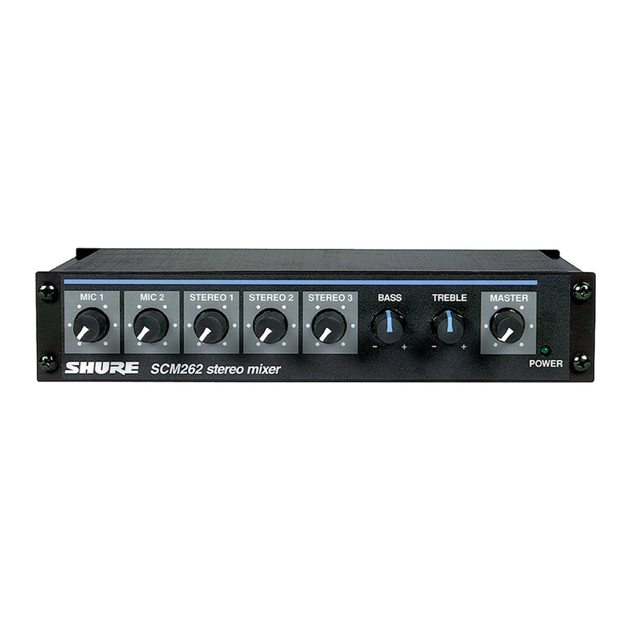
SCM262
Stereo Mixer
IMPORTANT SAFETY INSTRUCTIONS
1. READ these instructions.
2. KEEP these instructions.
3. HEED all warnings.
4. FOLLOW all instructions.
5. DO NOT use this apparatus near water.
6. CLEAN ONLY with dry cloth.
7. DO NOT block any ventilation openings. Allow sufficient distances for adequate ventilation and install in
accordance with the manufacturer's instructions.
8. DO NOT install near any heat sources such as open flames, radiators, heat registers, stoves, or other
apparatus (including amplifiers) that produce heat. Do not place any open flame sources on the product.
9. DO NOT defeat the safety purpose of the polarized or grounding type plug. A polarized plug has two
blades with one wider than the other. A grounding type plug has two blades and a third grounding prong.
The wider blade or the third prong are provided for your safety. If the provided plug does not fit into your
outlet, consult an electrician for replacement of the obsolete outlet.
10. PROTECT the power cord from being walked on or pinched, particularly at plugs, convenience receptacles,
and the point where they exit from the apparatus.
11. ONLY USE attachments/accessories specified by the manufacturer.
12. USE only with a cart, stand, tripod, bracket, or table specified by the manufacturer, or sold with the
apparatus. When a cart is used, use caution when moving the cart/apparatus combination to avoid injury
from tip-over.
13. UNPLUG this apparatus during lightning storms or when unused for long periods of time.
14. REFER all servicing to qualified service personnel. Servicing is required when the apparatus has been
damaged in any way, such as power supply cord or plug is damaged, liquid has been spilled or objects have
fallen into the apparatus, the apparatus has been exposed to rain or moisture, does not operate normally, or
has been dropped.
15. DO NOT expose the apparatus to dripping and splashing. DO NOT put objects filled with liquids, such as
vases, on the apparatus.
16. The MAINS plug or an appliance coupler shall remain readily operable.
17. The airborne noise of the Apparatus does not exceed 70dB (A).
18. Apparatus with CLASS I construction shall be connected to a MAINS socket outlet with a protective earthing
connection.
19. To reduce the risk of fire or electric shock, do not expose this apparatus to rain or moisture.
20. Do not attempt to modify this product. Doing so could result in personal injury and/or product failure.
21. Operate this product within its specified operating temperature range.
Advertisement
Table of Contents

Related Manuals for Shure SCM262


Summary of Contents for Shure SCM262
-
Page 1: Stereo Mixer
Publications SCM262 Stereo Mixer IMPORTANT SAFETY INSTRUCTIONS 1. READ these instructions. 2. KEEP these instructions. 3. HEED all warnings. 4. FOLLOW all instructions. 5. DO NOT use this apparatus near water. 6. CLEAN ONLY with dry cloth. 7. DO NOT block any ventilation openings. Allow sufficient distances for adequate ventilation and install in accordance with the manufacturer’s instructions. -
Page 2: General Description
WARNING: This product contains a chemical known to the State of California to cause cancer and birth defects or other reproductive harm. General Description The Shure Model SCM262 is a stereo mixer intended for sound reinforcement applications that integrate microphones with consumer stereo products. It incorporates two active-balanced microphone inputs with three unbalanced stereo aux level inputs. -
Page 3: Rear Panel
Lights up to indicate when the unit is plugged in and receiving power. The SCM262 does not have a power switch. To turn the unit off, unplug the power cord or use an external power strip with a switch. However, it can remain plugged in as it uses very little power when idle. -
Page 4: Dip Switches
③ These phono jacks are stereo, unbalanced outputs for use with consumer stereo equipment. DIP Switches. ④ These allow you to adjust the SCM262 for specific applications. See DIP Switches. Left/Right STEREO INPUTS, 1-3. ⑤ These phono jacks are stereo inputs for connection to consumer stereo devices. - Page 5 Publications DIP SWITCH FUNCTION POSITION UP (default) POSITION DOWN...
- Page 6 Publications DIP SWITCH FUNCTION POSITION UP (default) POSITION DOWN LEFT OUTPUT MIC/LINE Line RIGHT OUTPUT MIC/LINE Line MIC 1 DUCKING MIC 2 DUCKING DUCKING LEVEL –∞ -20 dB STEREO 3 JUKEBOX MUTE...
-
Page 7: General Application
LEFT/RIGHT OUTPUT MIC/LINE: DIP switches 1 and 2 adjust the left and right outputs for line- or mic-level operation. MIC 1/MIC 2 Ducking: When ducking is on, the SCM262 will automatically lower the gain of all STEREO inputs when someone is speaking into one of the microphones. - Page 8 STEREO 1 and 2 channels. This way, a CD player can be playing music, and then when someone plays a song on the Jukebox, the SCM262 will automatically mute the CD player channels and switch to the Jukebox. STEREO 1 and 2 channels will remain muted for about 30 seconds after program material is finished, to allow the jukebox time to move on to the next song.
-
Page 9: Internal Modifications
Publications Internal Modifications Internal Modifications Voltages in this equipment are hazardous to life. No user-serviceable parts inside. Refer all servicing and modifications to qualified service personnel. Disassembly To access the printed circuit board (pc board) for internal modifications, use the following steps: 1. - Page 10 Publications When reassembling the SCM262, DO NOT OVERTIGHTEN the knob retainer nuts. Use a minimal amount of force to secure the nut (0.6-0.8 N-m (5-7 in-lb)). Damage to the internal components will result if too much force is used.
- Page 11 Publications Capacitor Value Corner Frequency .033 µF 803 Hz .047 µF 564 Hz .068 µF 390 Hz .1 µF 265 Hz .22 µF 120 Hz Capacitor Value Corner Frequency .33 µF 80 Hz .47 µF 56 Hz .68 µF 39 Hz 1.0 µF 26.5 Hz...
- Page 12 The aux ducking depth may be changed by removing resistor R213 and inserting a resistor into jumper X202. Publications Use the following tables to determine the proper resistor value for the desired ducking depth. Ducking Depth Resistor Value 6 dB 4,000 Ω...
-
Page 13: Supplied Hardware
Publications Ducking Depth Resistor Value 36 dB 20,000 Ω 42 dB 25,000 Ω 47 dB 30,000 Ω 50 dB 33,000 Ω 55 dB 40,000 Ω Ducking Threshold This modification adjusts the threshold for activating the ducking circuit. The ducking threshold can be raised or lowered by first removing resistor R333, and then placing a resistor (R) at jumper X303. -
Page 14: Rackmount Installation
Single unit (half-rack) installation: 1. Attach the short and long rackmount brackets to the SCM262 with eight (8) of the supplied bracket screws. Dual-mounted installation: 1. Connect the two units together side-by-side using two (2) straddle brackets. The brackets should straddle the recessed edges on the top and bottom of each chassis. -
Page 15: Stand-Alone Installation
Fixed Installation To permanently affix the SCM262 above or below a table, shelf, or counter top, use the following steps: 1. Fasten the straddle brackets to the recessed edges of the chassis using four (4) bracket screws. -
Page 16: Specifications
Publications Specifications Frequency Response at 1 kHz Mic/Line Switch 150 Hz to 20 kHz ±2 dB Aux Input 20 Hz to 20 kHz ±2 dB Low-Cut Filter -6 dB/octave below 80 Hz Total Harmonic Distortion 1 kHz, +4 dBu out, mix output (MASTER) at +0 dB <0.25% Equivalent Input Noise 150 Ω... - Page 17 channel controls full counterclockwise, A-Weighted Publications Master full counterclockwise -95 dBV Master full clockwise -59 dBV Common Mode Rejection >70 dB, at 1 kHz Polarity All inputs to all outputs are non-inverting. Overload and Shorting Protection Shorting outputs, even for prolonged periods, causes no damage.Microphone inputs are not damaged by signals up to +10 dBV;...
- Page 18 SCM262 Publications 100–200 V AC, 50/60 Hz, 60 mA SCM262E 220–240 V AC, 50/60 Hz, 30 mA Temperature Range Operating Temperature -7° – 49° C (20° –120° F) Storage Temperature -29° – 74° C (-20° –165° F) Dimensions 43 x 218 x 162 mm (1.72 x 8.60 x 6.37 in.) Net Weight 1.1 kg (2 lbs, 5 oz.)
- Page 19 Publications Input Output Line Low-impedance mic (150 Ω) 32 dB 72 dB 60 dB Line -9 dB 31 dB 19 dB Stereo -5 dB 35 dB 23 dB Inputs Input Impedance Designed for use with Actual (typical) Input Clipping Level...
- Page 20 Publications Input Impedance Designed for use with Actual (typical) Input Clipping Level Mic (XLR) <600 Ω 1.4 kΩ -16 dBV Line <10 kΩ 155 kΩ +24 dBV Stereo <2 kΩ 21 kΩ >28 dBV Outputs Output Impedance Designed for use with Actual (typical) Output Clipping Level...
-
Page 21: Replacement Parts
Line >5 kΩ 300 Ω +18 dBV ≥10 kΩ 1.5 kΩ +5 dBV Replacement Parts Knob, Master (blue) 95B8752 Knob, Channel Gain (white) 95A8752 Line (Power) Cords: SCM262: 100-120 Vac (US/Canada) 95B8762 Line (Power) Cords: SCM262E: 220-240 Vac (EU) 95B8778... -
Page 22: Optional Accessories
Line (Power) Cord, 230-240 Vac (UK) 95A8713 Service Statement For additional service or parts information, please contact Shure's Service department at 1-800-516-2525. Outside the United States, please contact your authorized Shure Service Center. Certifications This product meets the Essential Requirements of all relevant European directives and is eligible for CE marking. - Page 23 Email: info@shure.de Publications...
Need help?
Do you have a question about the SCM262 and is the answer not in the manual?
Questions and answers