Advertisement
Advertisement
Table of Contents

Summary of Contents for R1 WURKS LCG Digital-3 2S/1S
- Page 1 INSTRUCTION MANUAL...
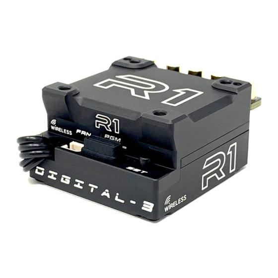
- Page 2 1. Introduction New from R1 Motor lab is the LCG Digital-3 2S/1S Wireless* programmable brushless speed controller. Developed using the most advanced MICROCHIP processor and a robust proprietary software, the LCG Digital-3 delivers the most technologically advanced features to date. Development of the LCG Digital-3 was focused on ultra smooth power delivery needed for modified racing as well as supreme power efficiency for our class leading line of Stock Motors.
- Page 3 4. Connection Caution For maximum performance, the black silicon wire without any connector is 12AWG. For soldering the battery and motor wires onto the solder bar, set the iron to a minimum of 60W. Avoid soldering more than 5 seconds or the ESC may overheat and become damaged.
-
Page 4: Transmitter Settings
Battery Wire Connection When connecting the battery, pay attention to polarity: incorrect connection will damage the ESC. (The battery is not covered by the warranty.) As shown in the figure above, connect the positive (+) wire is connected to (+) battery port, and the negative (-) wire is connected to the (-) battery port. - Page 5 CALIBRATION TO TRANSMITTER Turn the transmitter on and place the throttle on the neutral. Connect the ESC to the battery. Turn the ESC power switch ON LED turns on when throttle is moved forward to the maximum. “Acceleration Full Position Save”...
-
Page 6: Programmable Items
8. Programmable Items Set detailed setting parameters and check racing information and telemetry data using the WiFi module. Connect the WiFi module using the 3pin connector on the front of the ESC. Refer to WiFi module manuals for specific information on those components. - Page 7 Motor-Wiring A-B-C / C-B-A A-B-C Units Metric / English Metric Download All parameters inside the setup card are downloaded to the ESC. Factory Setting Change the setting of ESC to default factory status. Current Voltage XX.X Current Temp 0° ~ 135°C Max Temperature 0°...
- Page 8 and RPM but also cause high heating. So, excessive setting could cause fatal problems to the ESC and motor. TB (TURBO): should be activated when the throttle is located at 100%. (Boost setting + TB setting) are applied into timing.
- Page 9 and heating is increased. Turbo – Slope Set the amount of time it takes to recover from turbo speeds when the throttle is back to the original location. The lower the value, the more the brake effect and vehicle movement is decreased. Acceleration ...
-
Page 10: Fan Control
FAN Control In the Auto mode, it works depending on the ESC temperature and throttle position. In the On mode, it works all the time. Drag Brake Set the auto brake function to deliver a small brake effect at neutral position. Min Brake Amount ... -
Page 11: Motor-Wiring
B.E.C Voltage Set the voltage supplied to the receiver. Refer to the servo specifications for accurate voltage values, as the ESC may become irreparably damaged. 7.4V does not work when using a 1S battery. Motor Pole Num Set the motor poles. Incorrect pole setting could result in inaccurate maximum speed readings. Gear Ratio ... - Page 12 Maximum Speed Set a maximum speed limit. This speed will not be exceeded during drive time. Maximum RPM Set the maximum motor RPM limit. This level will not be exceeded during drive time. Error History M = Motor connection problem / motor malfunction / motor damage T1 = Temperature issue in ESC T2 = Temperature issue in motor S = Sensor problem...
-
Page 13: Specification
12. Specification DIGITAL-3 Motor Type Sensored / 4Pole Sensored Motor Limit >3.5T “Specification when using the fan” Operating voltage 3.7-7.4V Forward / Brake / Reverse Full aluminum case / heat sink Typ. Voltage Drop @20A per phase 0.0048V Rated Current per phase 2549A Plugged 30x30x10mm Fan BEC Output...
Need help?
Do you have a question about the LCG Digital-3 2S/1S and is the answer not in the manual?
Questions and answers