Table of Contents
Advertisement
Advertisement
Table of Contents

Related Manuals for KIC SRA

Summary of Contents for KIC SRA
- Page 1 SRA Smart Reflow Analyzer Hardware Guide Publication Number SRA-330200-000...
- Page 2 There are no warranties with respect to the information contained in this document, express or implied, except as provided by written contract between KIC and the customer. All KIC product names and logos are trademarks of Embedded Designs, Inc. All other trademarks used herein are the property of their respective owners.
-
Page 3: Table Of Contents
SRA Smart Reflow Analyzer Hardware Guide SRA-330200-000 Table of Contents INTRODUCING THE SRA - SMART REFLOW ANALYZER .................... 1 SRA K ..............................2 EVIEW SRA S ..............................2 OFTWARE SRA HARDWARE INITIALIZATION ........................... 3 ..........................3 ARRANTY ROTECTION MPAIRMENT THE SRA LEDS ................................. 4 THE SMART DOCK LEDS............................ -
Page 4: Introducing The Sra - Smart Reflow Analyzer
The SRA Smart Reflow Analyzer raises the bar for Smart Factory systems and is another of the many smart devices and systems KIC offers to improve your production quality, productivity, and documentation. -
Page 5: Review Your Sra Kit
Review Your SRA Kit Upon receiving your SRA kit, check it to make sure that all the required components are there. The specific contents of your kit will match the configuration— datalog or wireless—that you ordered. The full catalog of parts appears below. -
Page 6: Sra Hardware Initialization
SRA Hardware Initialization To begin profiling in either datalog or Wi-Fi mode, you must first set up your SRA for use on your PC. Both modes communicate to the computer through a standard USB port – datalog mode uses a cable, Transmitter (Wi-Fi) mode uses the Smart Dock. -
Page 7: The Sra Leds
Flashing every 3 seconds when paired with Smart Dock Beacon Flashing Beacon mode starts when one sensor window is covered for >5 seconds. LED flashes until SRA finds a Smart Dock beacon and pairs with it to make private Wi-Fi connection. -
Page 8: The Smart Dock Leds
Alert Not Ready Solid On Cannot profile: due to TC 1 missing, TCs too hot, SRA module too hot, Battery too low, startup failure, voltage too low to charge or memory full. Plug into PC and software to identify alert. -
Page 9: The Sra Speed Detection Sensors
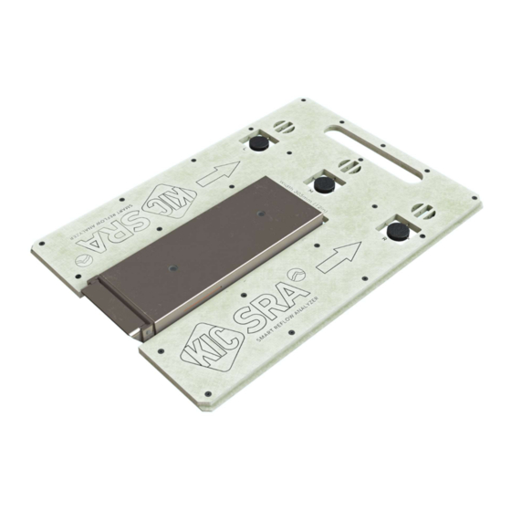
The SRA Speed Detection Sensors The SRA uses two (2) built-in sensors for automatic calculation of the conveyor speed during a profile. The top of the thermal shield has two access windows for these two sensors to project through when the shield lid is closed. -
Page 10: Power The Sra
SRA Smart Reflow Analyzer Hardware Guide SRA-330200-000 Power the SRA The SRA is powered by an internal NiMH battery pack. You charge the battery using the USB cable into your computer or the USB cable into the plugged-in AC charger. Typical Charging Time Normal Charge –... -
Page 11: Set Up The Sra
Set Up the SRA Once the Profiling Software 2G is installed and running, whenever you connect an SRA Smart Reflow Analyzer to a USB port, a message appears in the lower right of the screen reporting that it is detected. When you unplug the device, another message appears showing it has been disconnected from the PC. -
Page 12: Choosing The Mode Of Profiling
Launch Profiling Software 2G. Your Profiling Software USB Security Dongle is required to use all features in the software. Use the communication cable to connect the SRA to a USB port on the computer. A message appears confirming the SRA is detected. - Page 13 SRA Smart Reflow Analyzer Hardware Guide SRA-330200-000 The software shows the SRA as detected in the Profiling Hardware panel and displays radio button choices for specifying the communication mode. Click the radio button for Datalogger, followed by the Save (green check) button:...
- Page 14 Hardware Status button. The Hardware Status screen appears, showing the status of the device, and confirming that the software is connected to the SRA and receiving live readings. Note: The Device panel displays live temperature values and the current battery voltage. TC connections display the live temperature or appear as open (opn) if there is no reading from that TC.
-
Page 15: Wireless Mode
A message appears confirming the SRA is detected. From the Main screen, click on the Globe button to display the Global Preferences screen. The software shows the SRA as detected in the Profiling Hardware panel and displays radio button choices for specifying the communication mode. - Page 16 Tap the Smart Dock and then cover either one of the two (2) SRA speed sensor windows on top of the SRA for at least 5 seconds to start the pairing. 10. The ANT blue LED on both devices flashes until the devices are paired.
- Page 17 SRA Smart Reflow Analyzer Hardware Guide SRA-330200-000 12. When the Main screen appears, click the Hardware Status button. 13. The Hardware Status screen appears, showing the status of the device, and confirming that the software is receiving the live Wi-Fi signal from the SRA.
-
Page 18: Hardware Status: Led Status Window
With the SRA connect you can access an LED Status Window from the Hardware Status screen by clicking on the blue logo to the left of the Device panel. This pop up window will indicate the matching status of the SRA LEDs on the SRA hardware, along with brief status descriptions. -
Page 19: Thermal Protection
SRA Smart Reflow Analyzer Hardware Guide SRA-330200-000 Thermal Protection The SRA Smart Reflow Analyzer includes a built-in thermal shield—a stainless steel enclosure that protects the internal electronics (SRA module) against extreme heat during runs through a thermal process. Caution: The SRA module’s maximum internal temperature is 85... -
Page 20: Safe Handling After Exiting The Oven
Safe Handling after Exiting the Oven As the SRA emerges from the oven, the pallet and shield will be hot to the touch. Your kit includes a pair of safety gloves, and it is absolutely required that you use these gloves for handling the unit after an oven run. -
Page 21: Safely Opening The Shield
USB cable to the SRA module as the data is wirelessly downloaded via the Smart Dock. It is recommended to place the SRA in front of a fan or other cooling station arrangement to aid in the cooling process. -
Page 22: Specifications And Normal Environmental Conditions
75% isopropyl alcohol solution. Use a swab to clean narrow spaces around the button and connector. Do not use abrasive compounds on any part of the chassis, as they may damage it. Be sure to keep the speed sensor windows on both the SRA module and thermal shield cover clean of dust and debris to ensure proper operation. -
Page 23: Regulatory Compliance
RF Exposure statement: To comply with FCC RF exposure requirements, a separation distance of at least 20cm must be maintained between the SRA Smart Flow Analyzer and all persons when WiFi data is being transmitted. -
Page 24: Calibrating The Sra
Reinstallation of SRA module into main assembly The CJREF offset is the amount of temperature to add or subtract from the base profiler readings. KIC recommends setting this value to the same temperature as the CJREF (Internal) temperature. You can view the CJREF (Internal) temperature by clicking the Get Current TC button on the Calibration Log screen displayed during the procedure. -
Page 25: Remove Sra Module
Connect the SRA module to the computer USB port. (The device should power on automatically when connected to the PC.) Connect the calibration adapter cables to the SRA module, making sure to note the orientation of the connector. The side of the connectors stamped with the word ‘Top’ should face up. Either connector can plug into either slot of the SRA module. - Page 26 Note: When the software utility is open and the hardware connected, if the SRA name does not appear in the Device field, clicking the Refresh button forces the utility to search for the presence of the hardware and display the name in the field if found: 10.
-
Page 27: Specify The Cjref Offset
SRA Smart Reflow Analyzer Hardware Guide SRA-330200-000 Specify the CJREF offset Open the SRA Hardware Utility - Calibration screen. In the CJREF Offset panel’s Calibrate Temperature field, accept the recommended default temperature of 25°C (77°F) or type in a new value between 10°C (50°F) and 500°C (932°F). -
Page 28: Specify The Gain Adjustment
Note: Older versions of KIC software may indicate other values as the default temperature. Adjust the output on the thermocouple simulator to match your specified calibration temperature. -
Page 29: Reinstall Sra Module
SRA-330200-000 Reinstall SRA Module Reinsert the two (2) connectors from the main assembly into the front of the SRA module. NOTE: Be sure to take note of orientation of connectors – A to A, B to B. Position the SRA module in place inside the main assembly... -
Page 30: Contact Kic
Asia: asia.tech@kicmail.com KIC Service/Repair All service and repair of the SPS Smart Profiler or Smart Dock, other than the calibration, requires contacting a KIC Service center and having the service/repair conducted by personnel authorized by KIC. KIC Product Training Contact KIC Customer Support by email, training@kicmail.com...
Need help?
Do you have a question about the SRA and is the answer not in the manual?
Questions and answers