Advertisement
Quick Links
Instructions
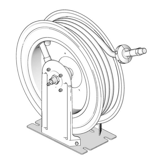
XD30 Series High
Capacity Hose
Reels
Used in applications requiring long range dispense, transfer or evacuation of fuels, air,
water, lubricants and other automotive fluids such as oil, grease and transmission fluids.
For professional use only.
Not for use in explosive atmospheres.
Application markets include: mobile equipment servic-
ing, heavy construction and industrial plants.
HS Models: Page 3
HN Models: Page 4
HN Models
Important Safety Instructions
Read all warnings and instructions in this
manual. Save these instructions.
HS Models
3A0138J
EN
ti13980
Advertisement

Related Manuals for Graco XD30 Series

Summary of Contents for Graco XD30 Series
- Page 1 Instructions XD30 Series High Capacity Hose 3A0138J Reels Used in applications requiring long range dispense, transfer or evacuation of fuels, air, water, lubricants and other automotive fluids such as oil, grease and transmission fluids. For professional use only. Not for use in explosive atmospheres.
- Page 2 Warnings Warnings The following warnings are for the setup, use, grounding, maintenance, and repair of this equipment. The exclama- tion point symbol alerts you to a general warning and the hazard symbol refers to procedure-specific risk. Refer back to these warnings. Additional, product-specific warnings may be found throughout the body of this manual where applicable.
- Page 3 Warnings WARNING MOVING PARTS HAZARD Moving parts can pinch, cut or amputate fingers and other body parts. • Keep clear of moving parts. • Do not operate equipment with protective guards or covers removed. • Pressurized equipment can start without warning. Before checking, moving, or servicing equip- ment, follow the Pressure Relief Procedure and disconnect all power sources.
- Page 4 Warnings HN Models Each model shown in the table below is available in several colors. The last character of each model no. indicates the hose reel color. A = white, B = Metallic Blue, F = Yellow, and G = Desert Sand. On the table below, this last character is represented by the generic # symbol.
-
Page 5: Typical Installation Layout
Installation Installation A ground wire (G), bleed-type master air valve (E), thermal relief valve (H) and fluid drain valve (J) are required in your system installation. These (user supplied) components help reduce the risk of serious injury. • The ground wire (G) must be connected to the pump grounding lug and to a true earth ground to prevent static sparking that could result when fluid is dispensed through the hose. -
Page 6: Pressure Relief Procedure
Installation Pressure Relief Procedure 3A0138J... - Page 7 Installation All Mountings To reduce the risk of injury, be sure the mounting sur- face and mounting screws are strong enough to sup- port the reels, weight of the fluids and stress caused by hard pulls on the service hoses. See Technical Data, page 23 for weights of hose reel assemblies.
-
Page 8: Wall Mounting
Installation Wall Mounting 1. A = Screws 2. A = Screws Maximum distance to floor - 16 ft (4.87 m) ti13983 ti13982 Ceiling Mounting 1. A = Screws 2. A = Screws Maximum distance to floor - 16 ft (4.87 m) 3A0138J... - Page 9 Installation Truck Bed Mounting 1. A = Screws Changing Position of Guide Arms (30) HS Models Only 2. Reinstall nuts (33). Torque to 25 - 35 ft lbs (33.9 to 1. Remove nuts (33). Reposition guide arms (30) to · 47.5 N new location.
- Page 10 Installation Changing Hose Guide (31) Position HS Models Only. 2. Reinstall screws (52) and nuts (53) (not shown). 1. Remove screws (52) and nuts (53) (not shown). · Torque to 25 - 35 ft lbs (33.9 to 47.5 N Reposition hose guide (31) to new location. 3A0138J...
- Page 11 Installation Flushing Before installing meter or dispense valve to end of hose, flush supply line with a solvent compatible with the fluid you are dispensing. Place end of hose in waste container. Blow out entire lubricant supply line with air. Flush equipment with a compatible solvent until fluid Pump dispensing lubricant through line until all sol- runs clear.
- Page 12 Adjusting Spring Tension Adjusting Spring Tension Increasing Spring Tension The spring is always under great tension, which if released in an uncontrolled manner could cause seri- ous injury. • Never allow the reel to spin freely. Uncontrolled spinning could cause serious injury if you are hit by the hose.
- Page 13 Adjusting Spring Tension 3. Insert tool (C) in opening. Hold tool (C) firmly to 4. Turn tool (C) one full turn clockwise. engage spring force before removing screws (B). 5. Replace one screw (B). Leave tool (C) in place. 6. Remove tool (C). 7.
- Page 14 Adjusting Spring Tension Decreasing Spring Tension The spring is always under great tension, which if released in an uncontrolled manner could cause seri- ous injury. • Never allow the reel to spin freely. Uncontrolled spinning could cause serious injury if you are hit by the hose.
- Page 15 Adjusting Spring Tension 5. Replace one screw (B). Leave tool (C) in place. 6. Remove tool (C). 3A0138J...
- Page 16 Adjusting Spring Tension 7. Pull hose to test tension. Repeat 3 - 7 if necessary. 8. Replace and tighten screws (B) and (A). 3A0138J...
- Page 17 Hose Stopper Installation Hose Stopper Installation ti13525 Installing Meter 3A0138J...
- Page 18 Parts: HS Models Parts: HS Models (For a complete list of model numbers, see page 3) Ref. Ref. Part No. Description Part No. Description 24C986 HOSE, coupled, 50 ft (HSHC5 1‡ SHAFT, spring (not shown) models) 15Y781 WASHER, flat (not shown) 24C987 HOSE, coupled, 75 ft (HSLC8 mod- 3†...
- Page 19 Parts: HS Models Ref. Part No. Description 237873 STOP, hose (HSLD5 and HSMD5 models) 237874 STOP, hose (HSLE3 models) 50 SCREW, mach, phil, pn hd 51 NUT, hex, jam 111799 SCREW, cap, hex hd 16A390 NUT, hex 59 RATCHET, Aluminum 60## ASSEMBLY, high pressure swivel (HSHC5, HSHFF, HSPB8, HSHCD,...
- Page 20 Parts: HS Models Low/Medium Pressure Reels Only High Pressure Reels Only 3A0138J...
- Page 21 Parts: HN Models Parts: HN Models (For a complete list of model numbers, see page 4) Ref. Ref. Part No. Description Part No. Description 126076 HOSE, coupled, 75 ft (HNHB7 1‡ SHAFT, spring (not shown) models) 15Y781 WASHER, flat (not shown) 126075 HOSE, coupled, 50 ft (HNPC5 3†...
- Page 22 Parts: HN Models Ref. Ref. Part No. Description Part No. Description Included in Ratchet and Latch Replacement Kit Included in Low ? Medium Pressure Swivel Seal 24C995 Replacement Kit 24D134 ‡ Included in Spool Replacement Kit 24C998 ## Included in High Pressure Swivel Assembly Kit ...
-
Page 23: Technical Data
Technical Data Technical Data Maximum Pressure Inlet Outlet Model No. Application Hose Size (NPSM) (NPT) HSHC5# 1/2 in. x 50 ft. Grease 5000 34.5 1/2 inch 1/2 inch HNHC5# (12.7 mm x 1524 cm) HSHFF# Bare 5000 34.5 1/2 inch 3/8 inch HNHFF# HSLC8#... - Page 24 Technical Data Dimensions HS Models HN Models Model 229 mm 350 mm 546 mm 588.00 mm (9.0 in.) (13.77 in.) (21.5 in.) (23.10 in.) 229 mm 350 mm 561.73 mm 588.00 mm (9.0 in.) (13.77 in.) (22.12 in.) (23.10 in.) 3A0138J...
-
Page 25: Mounting Pattern
Technical Data Mounting Pattern 14 mm (1/2 in.) bolts - 4X 131.76 mm (5.187 in.) 293.86 mm (11.57 in.) 3A0138J... - Page 26 With the exception of any special, extended, or limited warranty published by Graco, Graco will, for a period from the date of sale as defined in the table below from the date of sale, repair or replace equipment covered by this warranty and determined by Graco to be defective.
Need help?
Do you have a question about the XD30 Series and is the answer not in the manual?
Questions and answers