
Subscribe to Our Youtube Channel
Summary of Contents for I.D. Systems UTP 1.0
- Page 1 UTP 1.0 INSTALLATION & VERIFICATION INSTRUCTIONS ©2017 I.D. Systems, Inc. 055-00000889 Rev B...
- Page 2 United States and other countries. It may not be reproduced, distributed, or altered in any fashion by any entity (either internal or external to I.D. Systems, except in accordance with applicable agreements, contracts, or licensing, without the express written consent of the Brand or Marketing Communications Director or the business management owner of the material.
- Page 3 UTP 1.0 Installation & Verification Instructions I.D. Systems www.id-systems.com/ Customer Support: 888-855-0913 I.D. Systems Confidential and Proprietary 055-00000889 Rev A...
-
Page 4: Table Of Contents
UTP 1.0 COMPONENTS ..........................4 REQUIRED TOOLS (NOT PROVIDED) ......................4 INSTALLATION STEPS ..........................5 LED INDICATORS ........................... 11 INSTALLING ON MULTIPLE VEHICLES AT THE SAME TIME ................. 12 UNINSTALLING THE UTP 1.0 ........................13 I.D. Systems Confidential and Proprietary 055-00000889 Rev A... -
Page 5: Overview
UTP 1.0 Installation & Verification Instructions Overview • This document details UTP 1.0 (remote vehicle monitoring and control hardware) installation and verification process. • Failure to follow the installation and verification processes may result in improper device operation and/or payment dispute for installation services. -
Page 6: Installation Steps
UTP 1.0 Installation & Verification Instructions Installation Steps NOTE: In all cases, safe location and secure mounting of the UTP 1.0 device is the installer’s primary concern. Installer is responsible for ensuring the UTP 1.0 device is safely and securely mounted and does not interfere with vehicle operation. - Page 7 OBD-II port. Make sure the connector is seated all the way down. After plugging it in, move the latch back to the closed position. Connector Latch Open Connector Latch Closed UTP 1.0 plugged into OBD-II port I.D. Systems Confidential and Proprietary 055-00000889 Rev A...
- Page 8 If the vehicle alarm should sound during installation, use the key fob to unlock the doors and disable the alarm. Once the UTP 1.0 connector is plugged in, the green LED light on the connector will begin to flash. It will take approximately 3.5 minutes to in-fleet successfully. (See Indicators for more information.)
- Page 9 UTP 1.0 Installation & Verification Instructions Do not install near brake / gas pedal area When tie wrapping the UTP 1.0 to the vehicle harness, wire tie both sides of the UTP 1.0 enclosure. Location of tie-wrap insert on enclosure Tie wraps fed through inserts on both ends of UTP 1.0...
- Page 10 UTP 1.0 securely tie wrapped onto wire harness. In this example, one side of the UTP 1.0 is tie wrapped and UTP cable is tie wrapped onto the wire harness as well. I.D. Systems Confidential and Proprietary...
- Page 11 Final Install Validation: Make sure the UTP 1.0 enclosure is tucked in behind the panel and not visible to the customer. Double check to make sure the UTP 1.0 is tie wrapped securely to a wire harness and away from the gas/brake pedal area.
-
Page 12: Led Indicators
Slow blink = no cellular Solid on = install successful Solid on = install failure If both LEDs are… OFF after install = Normal OFF at install = No power ON = Fatal exception I.D. Systems Confidential and Proprietary 055-00000889 Rev A... -
Page 13: Installing On Multiple Vehicles At The Same Time
Go back to the first car and make sure the LED on the UTP connector has turned solid green (indicating successful In-Fleet). Once the UTP 1.0 LED has turned solid green, use two wire ties to attach the UTP 1.0 to a wire harness under the dash panel. -
Page 14: Uninstalling The Utp 1.0
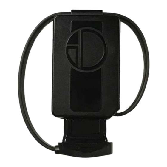
Uninstalling the UTP 1.0 To safely uninstall the UTP 1.0, follow these steps: Use the built-in tie wrap cutting feature on both side of the UTP 1.0 when cutting/removing tie wraps, so as not to damage the wire harness or the UTP 1.0 enclosure. - Page 15 Move the OBD-II connector latch to the open position and unplug the OBD-II connector from the vehicle OBD-II port. Coil the UTP 1.0 cable, securing it to the enclosure, and fasten the OBD-II connector onto the receptacle on the enclosure. Move the latch to the closed position.
Need help?
Do you have a question about the UTP 1.0 and is the answer not in the manual?
Questions and answers