Advertisement
Installation Instructions
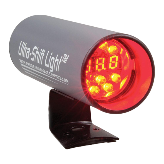
Ultra-Shift Light With RPM Activated Window Switch
PRECAUTIONS:
Read ALL instructions before installing instrument.
Follow ALL safety precautions when working on vehicle-wear safety
glasses!
ALWAYS disconnect (-) negative battery cable before making
electrical connections.
HELP?:
If after reading these instructions you don't fully understand how to
install your instrument(s), contact your local Stewart Warner
distributor, or contact our Technical Support Team toll free at
1 866-797-7223 (SWP-RACE).
www.SW-Performance.com
Visit
GENERAL APPLICATION:
12-volt DC negative (-) ground electrical systems (11-20 VDC
operating voltage range).
The upper rpm limit of the shift light is variable, dependent upon the
PPR setting. The upper RPM limit for the PPR settings are .5-2 PPR=
18,000 RPM, 2.5-4 PPR= 15,000 RPM, and 5-6 PPR= 13,000 RPM.
Programmable RPM dependent switched output that will sink
(ground) 1 amp maximum (short circuit protected).
Figure 1
NEVER CONNECT GREEN WIRE TO THE COIL
WHEN USING AN MSD OR SIMILAR HIGH
OUTPUT CAPACITIVE DISCHARGE STYLE
IGNITION SYSTEM
Damage to the shift light will occur—Connect GREEN wire
to the tachometer terminal only
SET-UP MENU, OPTIONS, & DESCRIPTIONS:
The Set-up Menu sets the different options and calibrations to establish
the overall operation of the Ultra-Shift Light™, and should be set up
before the RPM window switch option is used.
ShP – Sets shift point RPM.
NOTE: The upper rpm limit of the shift light is variable, and depends
upon the PPR setting. The upper RPM limit for the PPR settings are
.5-2 PPR= 18,000 RPM, 2.5-4 PPR= 15,000 RPM, and 5-6 PPR=
13,000 RPM.
Disp – Display options (0n, 0ff). This determines the information
shown on the display.
•
0n - Current engine RPM is shown on the display.
•
0ff - Nothing displayed. Recall information can still be viewed.
ppr – Pulses/revolution of the tach signal (. 5 , 1 , 1 . 5 , 2, 2. 5 , 3, 4, 5, 6).
WARNING: An improper PPR setting will cause the RPM display, shift
light activation, and switch activation to be inaccurate.
L0 – Set switched output activation RPM (Range: 500 to18. 0 0).
HI – Set switched output deactivation RPM (Range: l0 setting
to18. 0 0).
118799
Rev 1: 10/10/04
for additional information.
1
.
3
5
SHIFT-LIGHT MOUNTING:
Ultra-Shift Light
The
may be mounted on a roll cage, steering
column, dash, or other locations of high visibility.
Ultra-Shift Light
To mount the
or secure using a hose clamp.
To mount on an existing tachometer, loosen the mounting strap and
Ultra-Shift Light
insert the base of the
retighten the mounting strap.
SHIFT-LIGHT WIRING (FIGURE 1):
1.
Disconnect negative (-) battery cable.
2.
Using 18-ga. wire, connect the (BLACK) wire to a clean (rust/paint-
free) ground, preferably battery negative terminal.
3.
Using 18-ga. wire, connect the (RED) wire to a switched +12V
source, like the ignition wire.
4.
Using 18-ga. wire, connect the (GREEN) wire the coil negative or
the tachometer terminal of the ignition module.
5.
Using 18-ga. wire, connect the (WHITE) wire to the relay coil
negative. This wire will supply the ground (1 amp maximum) to
energize the relay and activate the desired device.
NOTE: The (WHITE) wire provides an output (switched to ground)
whenever the engine RPM is between the programmable L0 and HI
set points. This switch can be used to activate/deactivate any device
within a specific RPM range.
WARNING: Always use an, in-circuit
device controlled by the RPM window switch. In addition to the
"Arming"
switch, a wide-open-throttle switch MUST also be used
to deactivate a nitrous oxide, or similar system, when the engine is
no longer at wide-open-throttle.
6.
Reconnect the negative (-) battery.
ULTRA-SHIFT WITH RPM WINDOW SWITCH OPERATION:
Once the Ultra-Shift Light™ with RPM Window Switch is installed and
set up, the digital display, if Disp option is set to 0n, will show the
actual engine RPM, otherwise the display will be blank.
The peak RPM recall may be viewed at anytime during normal
operation. The peak RPM value is the maximum RPM attained since
the last time the peak was cleared.
1.
At any time during normal operation, display the max RPM
recall by pressing the
2.
The internal display will show PEAC then display the peak RPM.
3.
To clear the stored peak value, press and hold the
button. The display will read PEAC then display the peak RPM,
and then return to normal operation.
The shift indicator LED cluster will illuminate whenever the engine
RPM exceeds the programmable SHP RPM setting (refer to the Shift
RPM Setup section for programming information).
The shift indicator LED cluster brightness may be changed to one of
four levels at anytime during normal operation. These are used to
adjust to the changing racing conditions for the best visibility.
1.
To change the intensity of the LED cluster, press and hold
SELECT
button. The LED cluster will rotate through the four
levels.
2.
To select an intensity level, simply release the
when the LED cluster is at the desired intensity.
The switched output (WHITE) wire will switch to ground whenever
the engine RPM is between the programmable L0 and HI set points,
otherwise the output is off or floating (refer to the Window Switch
section programming and circuit wiring information). The switched
output may be used to control most any device where engine RPM is
a factor used to turn a device on or off, such as Nitrous Oxide
systems, CO2 and water sprayers for intercoolers, or even automatic
shifters.
SHIFT RPM SET-UP (Range 1000 to 18,000 RPM):
1.
Enter programming mode by pressing both
buttons at the same time, and then release both buttons.
2.
Scroll to the SHP parameter using the
SELECT
press the
button.
3.
The display will show the current shift point RPM (the default is 3000
RPM for a new shift light).
SCROLL
4.
Hold down the
down for one second, the value will increment quickly. Simply
SCROLL
release the
button and press it again to go back to
incrementing slowly. Press the
increment one step (10 RPM) at a time. If the desired shift RPM is
missed simply continue to hold the
will wrap around and start at 1000 RPM again.
NOTE: When scrolling above 9990 RPM, a decimal point will appear in
the center of the display to indicate that the far right digit will not be
displayed (refer to figure 2).
5.
Once the desired shift RPM is displayed, press the
return to the
MAIN MENU
6.
To exit programming mode, do not press any buttons for 5 seconds.
All changes will automatically store and the unit will return to normal
operation.
NOTE: The upper rpm limit of the shift light is variable, and depends
upon the PPR setting. The upper RPM limit for the PPR settings are
0.5-2
PPR=
18,000
RPM,
5-6 PPR= 13,000 RPM.
, use the bracket and screws provided,
bracket under strap and
"Arming"
switch to disable any
2
SCROLL
button.
SELECT
4
SCROLL
SCROLL
button, and then
button to increment slowly. After holding
SCROLL
button repeatedly to
SCROLL
button and the value
SELECT
.
2.5-4
PPR=
15,000
6
SCROLL
button
SELECT
&
button to
RPM,
and
Advertisement
Table of Contents

Subscribe to Our Youtube Channel
Related Manuals for Stewart Warner Ultra-Shift Light


Summary of Contents for Stewart Warner Ultra-Shift Light
- Page 1 The Set-up Menu sets the different options and calibrations to establish Enter programming mode by pressing both & the overall operation of the Ultra-Shift Light™, and should be set up buttons at the same time, and then release both buttons. SCROLL before the RPM window switch option is used.
- Page 2 (as indicated by the date code on the product). See activated so the system does not activate at low RPM when the detailed Warranty Policy for other Terms & Conditions. intercooler can easily cool the lower airflow. STEWART WARNER PERFORMANCE 1-866-SWP-RACE (797-7223) www.SW-Performance.com...
Need help?
Do you have a question about the Ultra-Shift Light and is the answer not in the manual?
Questions and answers