Advertisement
Quick Links
Installation Instructions
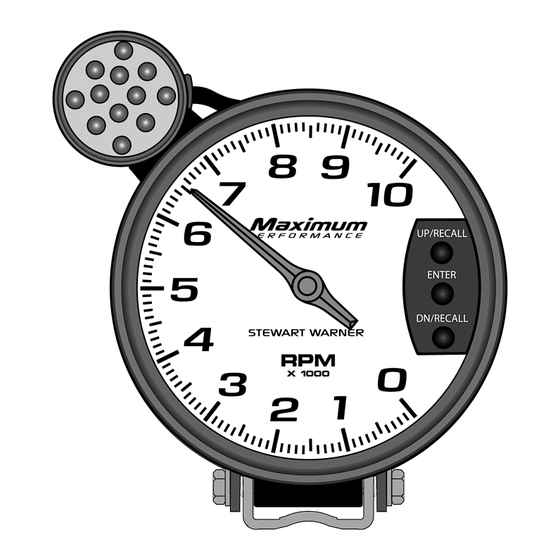
Memory/Shift Tachometer 3-3/8" & 5"
TACHOMETER MOUNTING (Figure 1 &2):
NOTE: Instructions apply to 3-3/8" & 5" Tachometer.
Recommended panel cut-out (hole size) for 3-3/8" tachometer
q
is 3-3/8".
Recommended panel cut-out (hole size) for 5" tachometer is 4-
q
5/8" if recessed to the bezel, or 3-3/8" if recessed to the step
(Figure 1).
Secure the tachometer in the hole using the supplied bracket
q
for the 3-3/8" and the 5". Remove the 3 Torx screws using a
T10 Torx driver. Insert the 3 studs and install lock washers and
nuts to secure the rear cover. Install the bracket as shown in
figure 2 and tighten the 3 locking nuts (5 in. Lb. max).
When mounting on the dash or roll cage or steering column,
q
use the cushioned strap & bracket as shown in figure 3.
Figure 1
Figure 3
NEVER CONNECT GREEN WIRE TO THE COIL WHEN USING AN MSD OR SIMILAR HIGH
OUTPUT CAPACITIVE DISCHARGE STYLE IGNITION SYSTEM
Damage to the tachometer will occur—Connect GREEN wire to the tachometer terminal only
B-755
115051
Rev 1: 9/17/02
1
3
5
PRECAUTIONS:
Read ALL instructions before installing instrument.
q
Follow ALL safety precautions when working on vehicle-wear
q
safety glasses!
ALWAYS disconnect (-) negative battery cable before making
q
electrical connections.
HELP?:
If after reading these instructions you don't fully understand
q
how to install your instrument(s), contact your local Stewart
Warner distributor, or contact our Technical Support Team toll
free at 1-866-797-7223 (SWP-RACE).
Additional
applications
q
www.SW-Performance.com.
GENERAL APPLICATION:
12-volt DC negative (-) ground electrical systems (11-20 VDC
q
operating voltage range for the tachometer, 11-16 VDC for the
Light bulb).
TACHOMETER WIRING (Figure 3):
1.
Disconnect negative (-) battery cable.
2.
Using 18-ga. wire, connect the (BLACK) wire to a clean
(rust/paint-free) ground, preferably battery negative terminal.
3.
Using 18-ga. wire, connect the (RED) wire to a switched +12V
source, like the ignition wire.
4.
Using 18-ga. wire, connect the (GREEN) wire to the coil
negative or the tachometer terminal of the ignition module.
5.
There are two (2) wires for the lighting. Connect the (WHITE)
lighting wire to the dash lighting circuit or to a +12V switched
circuit. Connect the (BLACK) lighting wire to a chassis ground.
6.
Calibrate the pulses per revolution (PPR). Refer to the
programming set-up section.
Reconnect the negative (-) battery cable & test instrument to
7.
ensure that it is working properly.
Figure 2
3-3/8" Installation
information
may
be
found
2
5" Installation
4
.
6
at
Advertisement

Subscribe to Our Youtube Channel
Related Manuals for Stewart Warner B-755


Summary of Contents for Stewart Warner B-755
- Page 1 B-755 PRECAUTIONS: Read ALL instructions before installing instrument. 115051 Follow ALL safety precautions when working on vehicle-wear Rev 1: 9/17/02 safety glasses! ALWAYS disconnect (-) negative battery cable before making Installation Instructions electrical connections. HELP?: Memory/Shift Tachometer 3-3/8” & 5”...
- Page 2 Press the Up/Clear or Down/Recall buttons to adjust for the SIGNAL INTERFACING: number of cylinders or pulses per rpm (the pointer will move to Stewart Warner Performance tachometers are designed to work with indicate the new setting). a wide variety of ignition types, including standard inductive [coil (-)
Need help?
Do you have a question about the B-755 and is the answer not in the manual?
Questions and answers