Sign In
Upload
Download
Table of Contents
Contents
Add to my manuals
Delete from my manuals
Share
URL of this page:
HTML Link:
Bookmark this page
Add
Manual will be automatically added to "My Manuals"
Print this page
×
Bookmark added
×
Added to my manuals
Manuals
Brands
Ducati Manuals
Gate Opener
HC 819
Installation manual
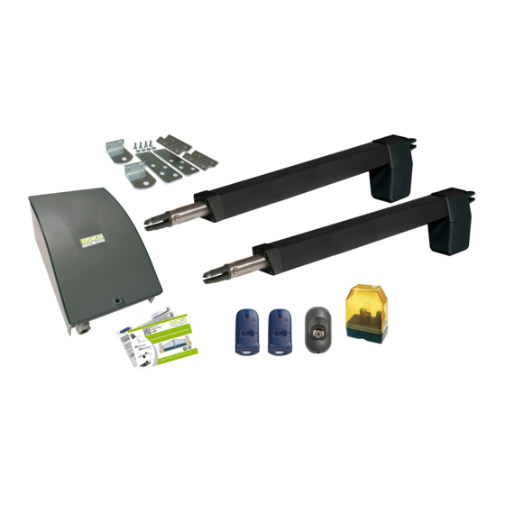
Ducati HC 819 Installation Manual
Swing gate opener
Hide thumbs
1
2
3
Table Of Contents
4
5
6
7
8
9
10
11
12
13
14
15
16
17
18
19
20
21
22
23
24
25
26
27
28
29
30
31
32
33
34
35
36
37
38
39
40
41
42
43
44
45
46
47
48
49
50
51
52
53
54
55
56
57
58
59
60
61
62
63
64
page
of
64
Go
/
64
Contents
Table of Contents
Bookmarks
Table of Contents
Table of Contents
General Installation Diagram
2 ) Preliminary Safety Warnings
1 ) General Characteristics
3 General Installation Scheme
4 ) Post Mounting Bracket
5 Front Mounting Bracket
Cth42
Cth42
Cth44
Cth44
Cth48
Key Switches
Photocells
Photocells
Advertisement
Quick Links
1
Table of Contents
2
General Installation Diagram
3
General Installation Scheme
4
4) Post Mounting Bracket
5
Cth42
6
Key Switches
Download this manual
W a t c h o u r
s u p p o r t v i d e o
KONTROL "large"
KONTROl "small"
S w i n g g a t e o p e n e r s I n s t a l l a t i o n m a n u a l
EVE actuators
HC actuators
certified
SW actuators
EN norms
R E V 1 0 2 9 - 1 1 - 1 6 E N G
d u c a t i h o m e . i t
Table of
Contents
Previous
Page
Next
Page
1
2
3
4
5
Advertisement
Table of Contents
Need help?
Do you have a question about the HC 819 and is the answer not in the manual?
Ask a question
Questions and answers
Related Manuals for Ducati HC 819
Gate Opener Ducati HC 812-400 SOLAR Installation Manual
Swing gate opener (64 pages)
Gate Opener Ducati Manual Slide User Manual
Sliding gate opener (28 pages)
Gate Opener Ducati SLIDE 446 Installation Instructions Manual
(34 pages)
Gate Opener Ducati SW400 Manual
(11 pages)
This manual is also suitable for:
Hc 812-300
Hc 812-400 solar
Hc 812-400 pro
Hc 812-600 pro
Hc 812-500 pro
Sw 7000
...
Show all
Sw 3000
Hc 812-400
Sw 7000 t
Sw 7000 t solar
Hc 812-300 solar
Evo 748
Evo 748 t
Evo 748 solar
Evo 748 t solar
Eve 01
Eve 01 t
Eve 01 solar
Eve 01 t solar
Table of Contents
Print
Rename the bookmark
Delete bookmark?
Delete from my manuals?
Login
Sign In
OR
Sign in with Facebook
Sign in with Google
Upload manual
Upload from disk
Upload from URL


Need help?
Do you have a question about the HC 819 and is the answer not in the manual?
Questions and answers