Advertisement
Introduction ..................................................................................................................................... 1
Assembly tips and information ........................................................................................................ 2
Assembly of the Octado .................................................................................................................. 3
Assembly of the mechanical dobby ............................................................................................... 24
Installing the electronic interface ................................................................................................... 35
Tips and tricks for using the loom .................................................................................................. 35
Trouble shooting ........................................................................................................................... 38
Warrantee and contact .................................................................................................................. 40
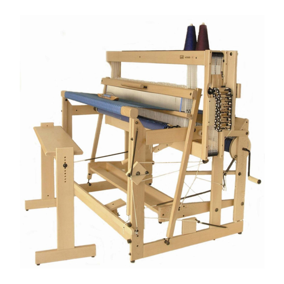
Octado
Instructions
Version: I_Octado_V4_EN
Advertisement

Related Manuals for Louet Octado


Summary of Contents for Louet Octado
-
Page 1: Table Of Contents
Octado Instructions Introduction ............................. 1 Assembly tips and information ......................2 Assembly of the Octado ........................3 Assembly of the mechanical dobby ....................24 Installing the electronic interface ....................35 Tips and tricks for using the loom ....................35 Trouble shooting ........................... 38 Warrantee and contact ........................ -
Page 3: Introduction
With the Octado, as the treadle is depressed, the rising shafts move, and as they rise, the back part of the loom also rises. This action automatically creates a shed of raised and lowered threads that is progressively greater toward the back and therefore completely even at the front in addition to equalizing tension on all warp threads. -
Page 4: Assembly Tips And Information
Assembly tips and information Barrel nuts For the assembly of the looms, we use many barrel nuts and bolts to connect parts. The cylinder shaped nuts have a slot on one of the flat sides. Always insert the barrel nut into the wooden part, so that the slot in the barrel nut is visible. -
Page 5: Assembly Of The Octado
Assembly of the Octado Octado parts per box The assembled castle of the loom is packed in box A. The handle for the beater is packed on top of the shafts. The parts shown here are packed in box B, together with the hardware bags, two wrenches and a screwdriver. - Page 6 1. Assembly of the side rails to the center frame Use sawhorses or a table to support the castle frame at least 25” (64 cm) above the floor. Open hardware bag # 1 containing the following: - 1 large ratchet - 1 screw 4.5 x 20 mm - 10 threaded rods m6 x132mm with cap nut, washer and barrel nut...
- Page 7 Octado has a second warp beam or a sectional warp beam. The two hinged arms are identical, however, as soon as you insert a carriage bolt into one, it becomes either a right hand or left hand hinged arm.
- Page 8 The left side rail can now be attached to the castle frame with two screws 5 x 40 mm. Insert these screws from inside through the side of the castle. Do not tighten the screws completely and allow the front screw about ¼” (5 mm) of clearance. This clearance is required to install the cloth beam later during the assembly process.
- Page 9 Take rear uprights AC and DB from box B and assemble to the lower side rails (connection A-A and B-B). Insure that the holes for the connections C, E, D and F are facing the same direction, so that the holes for the barrel nuts are at the same side of the connected parts.
- Page 10 Take the last screw out of the hardware bag, install it in the hole in the right side rail, and leave the head of the screw protruding approximately ¼” (5 mm). Hook the end of the Texsolv cord to the screw head.
- Page 11 For most weavers the lower position of the foot rail will be preferred. The frame of the Octado is complete and now you have to tighten the cap nuts of the connection between the right side rail and the castle.
- Page 12 Now turn the screw eyelet into the small side of the upright, until the entire threaded part is into the wood. Attach the right hand upright to the back beam with two screws 5 x 50 mm. Insert the long shaft of the warp beam through the right upright and slide the left upright onto the short shaft on the other side of the warp beam.
- Page 13 Put a carriage bolt through the hole in the hinged arm that is connected to the left side rail. First slide the large washer and then the two small washers onto the carriage bolt. Place the back part onto the protruding lower side rails and guide the carriage bolt of the hinged arms through the ball bearings of the left upright.
- Page 14 Take the two treadle sides from box B. Attach the buffers with the 4 x 21 mm screws onto the angled corners. Tap two of the m8 x 70 mm carriage bolts into the holes of a treadle side and slide on the large washers and 17 mm spacer bushings.
- Page 15 Install this rail with four screws in the same way and tighten the screws of both rails firmly with the screwdriver. 4. Attach the treadle and adjust the height of the dobby knife Open hardware bag # 3 with the following contents: - 1 heavy, big screw eyelet - 1 screw 4 x 17 mm...
- Page 16 Turn the knife pulley slightly by pulling on the cords and hook the end of the longest of the two Texsolv cords around the screw head on the knife pulley. Guide the cord one and a half turn around the knife pulley, clockwise, when looking from the front of the loom.
- Page 17 Insert the short cord into the marked hole, and then put it through its own end. Pull the short cord so that it is secured with a tight loop to the larger cord at the marked hole. Attach the end of the first cord, again with the hook, to the eye of the treadle.
- Page 18 Push the carriage bolt through the hole in the upright of the back part from the outside of the loom. Slide the large washer and the 36 mm spacer bushing over the carriage bolt. Place the barrel nut into the hole of the brake pedal and turn the threaded hook so far into the nut, that the threaded end sticks about 1-3/4”...
- Page 19 Hook the brake spring to both eyes. Position the large eye of the brake cable over the end of the carriage bolt and guide the cable one turn around the brake disk. Put the eye on the other end of the brake cable over the hook of the brake pedal while you push the brake pedal down.
- Page 20 You can adjust the friction of the cable and make the warp beam run just light enough by adjusting the length of the cord longer or shorter. It also makes a difference if the cord runs over the nuts or just besides the eye. You should hang the hook on the screw eye when not in use;...
- Page 21 Put two screws in each wooden post and one in the back of the upright. The heads of these screws need to stay ¼” (5 mm) above the wood. Connect the lower two screws on both sides of the loom with a cord. This cord will lock the breast beam to get an even tension when you attach the warp to the cloth beam.
- Page 22 Put two of the screw eyes in the appropriate holes in the sides of the loom, and hook the springs onto these eyes. By connecting the cords of the springs to the screws on the spring arms, you make the breast beam movable. You will use this system later to regulate the warp tension Put the two remaining screw eyes into the uprights of the back beam section.
- Page 23 Turn the black buffers into the top hole in the side rails of the loom. When you install a fly shuttle, you need to install these buffers into the bottom holes. Connect the lower reed tray (the one with the slanted side) to the uprights: Place the barrel nut into the hole on the end of the lower reed tray.
- Page 24 Put the hinges into the openings in the lower side rails. Assemble the handle to the upper reed holder: Slide a washer over the lag bolts and then put them through the holes in the upper reed holder. Next slide another washer and a spacer bushing over the lag bolts.
- Page 25 Hardware bag 6 is the same for Octado 70 (28”) Octado 90 (36”) and Octado 110 (44”). So with the Octado 70 and 90, you will have extra tie-up cords,...
-
Page 26: Assembly Of The Mechanical Dobby
Assembly of the mechanical dobby This part of the instruction manual can be ignored if your loom has an electronic interface. The mechanical dobby has a roller that is activated by a treadle. There is a chain with selection bars that runs over the dobby roller. - Page 27 Open the hardware bag: - 1 lag bolt m8 x 60 mm - 1 large washer m8 - 1 small washer m8 - 1 spacer bushing 22 mm long - 1 screw eye - 1 screws 4 x 17 mm - 2 black buffers with m6 threaded end - 2 carriage bolts m6 x 50 mm with washer and nut...
- Page 28 Slide the dobby mechanism over the carriage bolts, slip on the washers and tighten it with the nuts. The top hole in the dobby mechanism has the form of a slot. You can make use of this later when you adjust the proper distance between the dobby head and the dobby hooks.
- Page 29 Connecting the first to the last selection bar requires a bit of skill. The hinges of the connecting links, left and right, need to be pushed together at the same time. From the inside, insert a grey peg through the hinges until it comes through with a click.
- Page 30 Take the treadle and turn the screw eye in the hole at the end until the threaded part is completely into the wood. The picture shows how the eye needs to be located relative to the treadle. The 2 screw eyes should be screwed into the little holes at the bottom of the dobby treadle.
- Page 31 Put the shaft of the locking block in the hole of the lower side rail. Put a screw hook further back onto the side rail and hook the spring around it. Hook the end of the cord that goes to the locking block onto the threaded hook with knurled nut on the treadle and guide the cord over the pulley.
- Page 32 Next you slide the reversing disk onto the carriage bolt and tighten the cap nut. Turn the screw hook into the top of the upright and attach the spring of the reversing disk to it. Take the guide block with three pulleys and disassemble the carriage bolt with one pulley.
- Page 33 The bent piece of steel wire in the hardware bag is the anchor. The anchor will pull the dobby roller a quarter turn every time you depress the dobby treadle. Take the longer of the two cords. Put the end through the last hole in the other end to make a loop.
- Page 34 Guide the anchor cord from the top of the reversing disk behind the upright of the beater to the angled guide block with the pulleys. This cord needs to go around the higher of the two lower pulleys and then over the third pulley and up.
- Page 35 Guide the cord around the pulley, over the lower pulley of the angled guide block and to the reversing disk. Attach the cord in the same way to the two screws on the lower point of the reversing disk. Remove the cord from one or two pulleys;...
- Page 36 Move the spring to the middle of the brace. Now you can move the reversing disk a couple of mm. This is the same as the slack that the anchor has on the two rollers of the wooden knob. The average position of the brace, taking this slack into mind, has to be horizontal.
-
Page 37: Installing The Electronic Interface
Installing the electronic interface Please refer to the manual provided with the electronic interface for details on installing the electronic interface. Tips and tricks for using the loom Installing the heddles to the shafts With some weave structures there are many warp threads on the first two shafts. To help these two first shafts moving down when the shed closes, we have added some additional weight to these shafts. - Page 38 Remove the two twist ties that keep the upper part of heddles together. Pull the lower shaft end out of the lower shaft bar. Slide the bundle of heddles over the shaft bar. The heddles still have the lower two twist ties attached.
- Page 39 In order to prevent the back part of the loom from being pulled up during the beaming-up of the warp, you need to block the back part in its lowest position. If your Octado has a mechanical dobby, you can achieve this by taking off the spring that connects the blocking block to the frame of the loom.
-
Page 40: Trouble Shooting
Maintenance The Octado requires no special maintenance. However we do advise to check the tightness of all bolts, nuts and screws after a couple of months. This is particularly important when the loom is standing in a dry environment. - Page 41 blocking plate, the dobby hook remains extended forward and will be picked up by the knife, making next shed. One reason why this happens is that the shaft does not go down to its lowest position because it sticks to a shaft bar of the neighboring shaft. Leave some heddles at the ends of all the shafts. This will help to guide the shafts along each other.
-
Page 42: Warrantee And Contact
If you still have a question after reading this manual, please contact your dealer or Louët directly. Louët BV Phone: + 31 (0)573-252229 Kwinkweerd 139 Fax: + 31 (0)573-253858 7241 CW Lochem Email: info@louet.nl The Netherlands Website: www.louet.nl...
Need help?
Do you have a question about the Octado and is the answer not in the manual?
Questions and answers