Table of Contents
Advertisement
Quick Links
Q6SE Series
USER'S MAnUAl / InStAllAtIon InStRUctIonS
Single Package Heat Pump - Single Phase - R410A
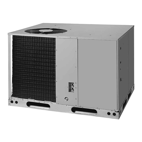
Premium Model Shown
It is your responsibility to know this product better than your customer. this includes being
able to install the product according to strict safety guidelines and instructing the customer on
how to operate and maintain the equipment for the life of the product. Safety should always be
the deciding factor when installing this product and using common sense plays an important
role as well. Pay attention to all safety warnings and any other special notes highlighted in the
manual. Improper installation of the furnace or failure to follow safety warnings could result in
serious injury, death, or property damage.
these instructions are primarily intended to assist qualified individuals experienced in the proper
installation of this appliance. Some local codes require licensed installation/service personnel
for this type of equipment. Please read all instructions carefully before starting the installation.
Return these instructions to the customer's package for future reference.
Do not DEStRoY. PlEASE READ cAREFUllY & KEEP In A SAFE PlAcE FoR FUtURE REFEREncE.
IMPoRtAnt
AttEntIon InStAllERS:
14 SEER
Advertisement
Table of Contents

Related Manuals for AC Pro Q6SE Series

Summary of Contents for AC Pro Q6SE Series
- Page 1 Q6SE Series 14 SEER USER’S MAnUAl / InStAllAtIon InStRUctIonS Single Package Heat Pump - Single Phase - R410A Premium Model Shown IMPoRtAnt AttEntIon InStAllERS: It is your responsibility to know this product better than your customer. this includes being able to install the product according to strict safety guidelines and instructing the customer on how to operate and maintain the equipment for the life of the product.
-
Page 2: Table Of Contents
USER InFoRMAtIon HEAt PUMP MAIntEnAncE ........4 IMPoRtAnt SAFEtY InFoRMAtIon ....3 Regular Cleaning............4 ABoUt tHE HEAt PUMP ........3 tRoUBlESHootInG ..........4 oPERAtInG InStRUctIonS .........3 WARRAntY InFoRMAtIon ........4 Cooling Operation ..........3 Operating the Heat Pump for Automatic Cooling and Heating Operation ..........3 Heating ..............4 Emergency Heat.............3 Operating the Indoor Blower Continuously .....4 Defrost Operation ...........3... -
Page 3: Important Safety Information
USER InFoRMAtIon oPERAtInG InStRUctIonS IMPoRtAnt SAFEtY InFoRMAtIon Please refer to the thermostat manufacturer’s User manual Please read all instructions before servicing this equipment. Pay attention to all safety warnings and any other special for detailed programming instructions. notes highlighted in the manual. Safety markings are cooling operation used frequently throughout this manual to designate a 1. -
Page 4: Heat Pump Maintenance
USER InFoRMAtIon HEAt PUMP MAIntEnAncE notE: While the ice and snow is melting, some steam may rise from the outdoor unit as the warm coil causes the melting frost to evaporate. When defrost is completed, the cAUtIon: outdoor fan motor will start, and the compressor will turn off again. -
Page 5: Important Safety Information
InStAllER InFoRMAtIon IMPoRtAnt SAFEtY InFoRMAtIon WARnInG: Safety markings are used frequently throughout this manual to designate a degree or level of seriousness and Do not place combustible material on or against should not be ignored. WARnInG indicates a potentially the unit cabinet. Do not place combustible hazardous situation that if not avoided, could result in materials, including gasoline and any other personal injury or death. -
Page 6: General Information
GEnERAl InFoRMAtIon Minimum Required Clearances to Obstructions The Q6SE series heat pump is designed only for outdoor rooftop or ground level installations. This unit has been 36" tested for capacity and efficiency in accordance with AHRI Standards and will provide many years of safe and dependable comfort, providing it is properly installed and maintained. -
Page 7: Air Filter Requirements
Air Filter Requirements HEAt PUMP InStAllAtIon Packaging Removal WARnInG: Remove the shipping carton and User’s Manual from the equipment. Take care not to damage the tubing connections never operate the unit without a filter in place. when removing the carton. For rooftop installations, remove Dust and lint could accumulate on internal parts, and discard the two supports attached beneath the unit. -
Page 8: Electrical Wiring
• Units require horizontal roof curb and return air kit for horizontal installations. • Ductwork should be attached directly to flanges on panels supplied in horizontal duct conversion kits. Rooftop Condensate Rooftop installations must be located according to local Drain building codes or ordinances and these requirements: •... -
Page 9: Grounding
Grounding and minimum size of electrical conductors and circuit protection must be in compliance with information listed WARnInG: on the outdoor unit data label. Any other wiring methods must be acceptable to authority having jurisdiction. the unit cabinet must have an uninterrupted or •... -
Page 10: Defrost Cycle Timer
• The standard defrost cycle will terminate after 13 minutes Recommended t-Stat Wire length and 39 seconds or when the coil temperature reaches (Unit to t-Stat) thermostat its terminate temperature, whichever occurs first. Wire Gauge 2-Wire 5-Wire • The defrost board is equipped with a 5 minute Anti-Short (Heating) (Heating/cooling) Cycle Delay (ASCD). -
Page 11: Start Up & Adjustments
StARt UP & ADjUStMEntS any unusual noises. If unusual sounds occur, determine the source of the noise and correct as necessary. Pre-Start check list 3. Allow the cooling system to operate for several minutes √ Verify the unit is level and allows condensate to drain. and then set the temperature selector above room √... -
Page 12: Heat Pump Maintenance
charging an R-410A Unit in Ac Mode HEAt PUMP MAIntEnAncE (With Outdoor Temperatures Above 65° F) 1. With the system operating at steady-state, measure the WARnInG: liquid refrigerant pressure in psig at the service valve. 2. Measure the liquid refrigerant temperature in Fahrenheit to prevent electrical shock, personal injury, or at the service valve. -
Page 13: Figures & Tables
FIGURES & tABlES 24.9 .75" NPT Female Drain Connector DOWNFLOW SUPPLY DUCT OPENING top View 47.5 13.5 13.5 13.3 23.5 DOWNFLOW RETURN DUCT OPENING HORIZONTAL SUPPLY DUCT CONDENSING OPENING HORIZONTAL COIL RETURN DUCT OPENING Back View 13.5 16.0 13.5 16.0 13.7 12.45 1 4/5... -
Page 14: Electrical Information
Electrical Information From Blower Relay Green Blue Brown Orange ECONOMIZER PLUG SEE ECONOMIZER INDOOR INSTALLATION THERMOSTAT INSTRUCTIONS SUB-BASE DEFROST ACCESSORY BOARD HEAT PLUG Typical Wiring (Field Supplied) for 1-Stage Cool, 1 Stage Electric Heat From Blower Relay Green Optional Green Outdoor Thermostat (Field Supplied) -
Page 15: Figure 8. Wiring Diagram For 208/230V Units
Figure 8. Wiring Diagram for 208/230V Units... -
Page 16: Cooling Charging Charts
cooling charging charts Q6SE-X24 CHARGING CHART - COOLING Remove refrigerant if above curve Add refrigerant if below curve Liquid Temperature (° F) Figure 9. charging chart for 2 ton Units Q6SE-X30 CHARGING CHART - COOLING Remove refrigerant if above curve Add refrigerant if below curve Liquid Temperature (°... -
Page 17: Figure 11. Charging Chart For 3 Ton Units
Q6SE-X36 CHARGING CHART - COOLING Remove refrigerant if above curve Add refrigerant if below curve Liquid Temperature (° F) Figure 11. charging chart for 3 ton Units Q6SE-X42 CHARGING CHART - COOLING Remove refrigerant if above curve Add refrigerant if below curve Liquid Temperature (°... -
Page 18: Figure 13. Charging Chart For 4 Ton Units
Q6SE-X48 CHARGING CHART - COOLING Remove refrigerant if above curve Add refrigerant if below curve Liquid Temperature (° F) Figure 13. charging chart for 4 ton Units Q6SE-X60 CHARGING CHART - COOLING Remove refrigerant if above curve Add refrigerant if below curve Liquid Temperature (°... -
Page 19: Airflow Data
Airflow Data ExtERnAl StAtIc PRESSURE DRoP - IncHES WAtER colUMn MoDEl nUMBER Q6SE- Tap T1 38.39 40.30 44.37 48.91 54.47 61.95 72.46 Tap T2 32.60 34.19 36.48 39.49 44.06 48.46 53.46 60.52 Tap T3* 1068 29.58 1010 31.28 33.36 34.87 38.81 42.52 46.88... -
Page 20: Installation / Performance Checklist
InStAllAtIon / PERFoRMAncE cHEcKlISt REFRIGERAtIon SYStEM InStAllAtIon ADDRESS: Was unit given 24 hr warm up period for crankcase heaters (if applicable)? CITY ________________________ STATE ________________ UNIT MODEL # ________________________________________ Stage-1 Liquid Pressure (high side) ________________________ UNIT SERIAL # ________________________________________ Stage-1 Suction Pressure (low side) ________________________ Unit Installed Minimum clearances per Figure 2 (page 6) ElEctRIcAl SYStEM...
Need help?
Do you have a question about the Q6SE Series and is the answer not in the manual?
Questions and answers