Table of Contents
Advertisement
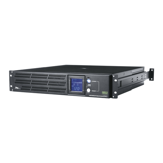
1000R and 2200R Series
Rackmounted Uninteruptible Power Supply
MODEL NUMBERS
• UPS-1000R
• UPS-1000R-IP
• UPS-1000R-8IP
• UPS-2200R
• UPS-2200R-IP
• UPS-2200R-8IP
THANK YOU
Thank you for purchasing the 1000R or 2200R Series Rackmounted UPS. The UPS provides battery
backup during power outages, automatic voltage regulation during periods of inconsistent utility power
and surge protection.
IMPORTANT
Please read this manual before removing the UPS from the shipping carton and before making any
connections to and operating your UPS.
USER MANUAL
I-00319
Rev N
Advertisement
Table of Contents
Troubleshooting

Related Manuals for Middle Atlantic Products 1000R Series


Summary of Contents for Middle Atlantic Products 1000R Series
- Page 1 USER MANUAL 1000R and 2200R Series Rackmounted Uninteruptible Power Supply MODEL NUMBERS • UPS-1000R • UPS-1000R-IP • UPS-1000R-8IP • UPS-2200R • UPS-2200R-IP • UPS-2200R-8IP THANK YOU Thank you for purchasing the 1000R or 2200R Series Rackmounted UPS. The UPS provides battery backup during power outages, automatic voltage regulation during periods of inconsistent utility power and surge protection.
-
Page 2: Table Of Contents
Important Safety Instructions ........3 - 4 Middle Atlantic Products Green Power UPS Technology ..... 5 FCC Warning . -
Page 3: Important Safety Instructions
IMPORTANT SAFETY INSTRUCTIONS READ AND SAVE THESE INSTRUCTIONS This manual contains important instructions that should be followed during installation and maintenance of the UPS and batteries. The lightning flash with the arrowhead symbol, within an equilateral triangle, is intended to alert the user to the presence of uninsulated dangerous voltage within the product’s enclosure that may be of sufficient magnitude to constitute a risk of electric shock. - Page 4 CONSIGNES DE SÉCURITÉ IMPORTANTES LIRE ET CONSERVER CES INSTRUCTIONS Ce manuel contient des instructions importantes à suivre lors de l'installation et de la maintenance de l'onduleur et des batteries. L'éclair avec le symbole de flèche dans un triangle équilatéral est destiné à alerter l'utilisateur de la présence d'une tension dangereuse non isolée dans l'enceinte du produit qui peut être d'une ampleur suffisante pour constituer un risque de choc électrique pour les personnes Le point d'exclamation dans un triangle équilatéral est destiné...
-
Page 5: Middle Atlantic Products Green Power Ups Technology
UPS will operate under Battery or AVR Mode. Under this condition, Green Power UPS and a traditional UPS would operate about the same. On average, utility power operates 88% of the time and the Middle Atlantic Products Green Power Technology will work in its money/energy saving Bypass Mode. -
Page 6: Circuit Diagram
FCC WARNING (CONTINUED) REMARQUE: Cet appareil a subi des tests de contrôle et a été déclaré conforme aux limites imposées aux appareils numériques de Classe B par la section 15 de la réglementation FCC. Ces limites ont été établies pour assurer une protection raisonnable contre les interférences indésirables lorsque l’appareil fonctionne dans un environnement résidentiel. -
Page 7: Unpacking And Parts List
UNPACKING AND PARTS LIST CAUTION: DO NOT LIFT THE UPS WHILE HOLDING THE FRONT FACE OF THE UNIT. THIS MAY DAMAGE THE UNIT. ALWAYS LIFT THE UPS BY HOLDING IT BY BOTH SIDES. ATTENTION: NE SOULEVEZ PAS L'UPS PAR LE FRONT DE L'UNITÉ COMME CELA PEUT ENTRAÎNER DOMMAGES. - Page 8 INSTALLATION AND MOUNTING (CONTINUED) CAUTION: THIS UNIT IS HEAVY, LIFT CAREFULLY ATTENTION: CET APPAREIL EST LOURD, SOULEVEZ AVEC ATTENTION One Person Installation: 1) Determine mounting location. 2) Install the Rear Mounting Brackets as shown. One Bracket is longer then the other to provide guidance when doing a one person installation.
-
Page 9: Front Panel Descriptions
FRONT PANEL DESCRIPTIONS LCD display: The LCD display indicates a variety of UPS operational conditions (see page 14 for LCD display definitions). Power Switch: On/off switch to turn UPS on and off. LCD display toggle button: Toggles between a variety of UPS operational conditions (see page 14). REAR PANEL DESCRIPTIONS - BANK OUTLETS Non-Critical Critical... - Page 10 REAR PANEL DESCRIPTIONS - BANK OUTLETS (CONTINUED) Non-Critical Critical Load Load Reset Input: Expansion Port Reset Wiring Fault 125V Surge Surge Protected Protected 60Hz 125V 60Hz 750W XXXX 1000VA Serial Port Reset Primary Secondary Expansion Port: Slot for Network Interface Card (NIC). Part Number UPS-IPCARD. (See pg 11 - 13 for installation steps) EPO (Emergency Power Off) Port: The EPO port may be used to connect the UPS to a contact closure switch or control system to enable emergency shutdown (see page 15).
-
Page 11: Rear Panel Descriptions (Individual Outlets)
REAR PANEL DESCRIPTIONS - INDIVIDUAL OUTLETS Non-Critical Critical Load Load Reset Input: Expansion Port Reset Wiring Fault 125V Surge Surge Protected Protected 60Hz 125V 60Hz 750W E325394 1000VA 6G48 Serial Port Reset Primary Secondary (CRITICAL OUTLETS) AC Outlets (Individually Controlled): All AC outlets provide connected equipment with AC line power, surge protection and line noise filtering during normal operation. - Page 12 REAR PANEL DESCRIPTIONS - INDIVIDUAL OUTLETS (CONTINUED) Non-Critical Critical Load Load Reset Input: Expansion Port Reset Wiring Fault 125V Surge Surge Protected Protected 60Hz 125V 60Hz 750W E325394 1000VA 6G48 Serial Port Reset Primary Secondary Expansion Port: Slot for optional Network Interface Card (NIC). Part Number UPS-IPCARD. (See pg 11 -13 for installation steps.
-
Page 13: Setup Of (Nic) Ups-Ipcard
2) After the installation is complete, run the “Middle Atlantic UPS-IPCARD Setup Utility” program. Under “All Programs”, select “Middle Atlantic Products > UPS-IPCARD”. 3) The main screen of the SNMP Card Configuration Tool program is shown in (FIGURE A). The configuration tool will display all Middle Atlantic UPS Network Interface Cards present on the network. - Page 14 SETTING UP UPS-IPCARD (CONTINUED) 4) Select the SNMP card you are setting up. Click on the Tools menu and select “Device Setup” or double click the SNMP card you want to configure. 5) You can modify the IP Address, Subnet Mask, and Gateway address for the Device MAC Address listed in the Device Network Settings window, as shown in (FIGURE B).
- Page 15 SETTING UP UPS-IPCARD (CONTINUED) Method 2: Using a Command Prompt 1) Obtain the MAC address from the label on the UPS Network Interface Card rear panel. Each UPS Network Interface Card has a unique MAC address. 2) Use the ARP command to set the IP address. Example: To assign the IP Address 192.168.20.240 for the UPS Network Interface Card, which has a MAC address of 00-0C-15-00-00-01 you will type in the following command prompt from a PC connected to the same network as the UPS Network Interface Card.
-
Page 16: Lcd Display Definitions
To clear the overload, first turn the power off on each equipment and unplug from the AC outlets one at a time, until the overload icon disappears and the alarm stops. Fault Icon: This icon appears if there is a problem with the UPS. Contact Middle Atlantic Products at 1-800-266-7225 for further help and support. -
Page 17: Battery Charging
BATTERY CHARGING The UPS is shipped from the factory with its internal battery fully charged. However, the battery may lose some charge during shipping and storage. Recharging the battery for at least four hours is recommended to ensure that the battery's maximum charge capacity is achieved. The UPS is equipped with an auto-charge feature. -
Page 18: Operation
OPERATION CAUTION: DO NOT plug a laser printer, copier, space heater, vacuum, paper shredder or other large electrical device into the UPS. The power demands of these devices will overload and possibly damage the UPS. ATTENTION: NE PAS brancher une imprimante laser, copieur, appareil de chauffage, vide, destructeur de papier ou d'un autre grand appareil électrique sur l'onduleur. -
Page 19: General Status Mode
GENERAL STATUS MODE 1) Press the Select button on the front panel to view each UPS status item listed in Table 1. Each item will display in the order shown. NOTE: The LCD display backlight will automatically turn off if the Select button is not pressed for more than 30 seconds. -
Page 20: Functions Setup Mode
FUNCTIONS SETUP MODE (CONTINUED) DEFAULT SETTING FUNCTION DESCRIPTION The time delay switching from battery mode to Delay Time line mode. There are 9 different settings: (0, 0.5, 1.0, 1.5, 2.0, 2.5, 3.0, 3.5, 4.0) seconds This function defines the number of external 0 (no external battery Number of Expansion battery packs connected to the UPS: (one - ten) -
Page 21: Battery Replacement
BATTERY REPLACEMENT Contact your dealer or call the number in this manual for information on battery replacement. Read and follow the IMPORTANT SAFETY INSTRUCTIONS before servicing the battery. Service the battery under the supervision of personnel who are knowledgeable about batteries and their precautions. Servicing of the battery can only be performed by trained personnel. - Page 22 BATTERY REPLACEMENT (CONTINUED) Contactez votre revendeur ou appeler le numéro dans ce manuel pour obtenir des informations sur le remplacement de la batterie. Lire et suivez les consignes de sécurité avant l'entretien de la batterie. Service uniquement la batterie avec la supervision du personnel avec bien informé sur les batteries et leurs précautions.
- Page 23 BATTERY REPLACEMENT (CONTINUED) CAUTION: The battery is heavy, use caution when removing ATTENTION: LA BATTERIE EST LOURD, SOYEZ PRUDENT LORSQUE VOUS RETIREZ 1) Power off the unit and disconnect it from its AC power source. 2) Remove the front panel by removing six screws then grasping it on the left hand side and pulling it away from the unit.
-
Page 24: Optional External Battery Connection
BATTERY REPLACEMENT (CONTINUED) 5) Remove three battery retaining screws (2 on left side, and 1 on the right side) and pull the battery out using the handle. REMOVE 2 SCREWS HANDLE REMOVE 1 SCREW 6) Insert replacement battery (Part No. UPS-RBP) and perform steps 2 - 4 in reverse. To reinstall the faceplate, reinstall six screws. -
Page 25: Troubleshooting
1. Battery is not fully charged. The UPS does not plugged in. perform the expected 2. Battery is degraded. 2. Contact Middle Atlantic Products about runtime. replacement batteries at 1-800-266-7225. 1. Turn the UPS off. Wait 10 seconds and 1. The on/off switch is designed then turn the UPS on. -
Page 26: Troubleshooting
TROUBLESHOOTING NETWORK INTERFACE CARD Problem Solution 1. Check the LED status, the normal condition is both yellow and green led is on. If green LED is off: Check if the UPS Network Interface Card is Unable to configure the UPS properly seated in the UPS and the UPS power is on. -
Page 27: Technical Specifications
TECHNICAL SPECIFICATIONS MODEL UPS-1000R Series UPS-2200R Series Capacity (VA) 1000 2150 Capacity (Watts) 1650 INPUT Cord Length & Plug Type 9ft. & NEMA 5-15P 9ft. & NEMA 5-20P 80 VAC - 150 VAC Input Voltage Range Input Frequency Range 50/60 Hz +/- 3 Hz (auto sensing) -
Page 28: Estimated Runtime
Built-in USB Interface ESTIMATED RUNTIME UPS-1000R SERIES ESTIMATED UNDER LOAD RUNTIME NOTE: The runtime values listed below are the maximum values. The actual runtime will be determined by the value set through the ‘Battery is Critically Low’ option in the Power Manager Software. Refer to the Power Manger Software User Manual, page 6. -
Page 29: Warranty
Voice: 613-836-2501 - Fax: 613-836-2690 / ca.middleatlantic.com - customerservicecanada@middleatlantic.ca Factory Distribution USA: NJ - CA - IL Canada: ON At Middle Atlantic Products we are always listening. Your comments are welcome. Middle Atlantic Products is an ISO 9001 and ISO 14001 Registered Company. Page 29... -
Page 30: Warranty Registration
WARRANTY REGISTRATION IMPORTANT NOTE Please register your purchase. http://www2.middleatlantic.com/ups/warranty/registration.aspx Page 30...
Need help?
Do you have a question about the 1000R Series and is the answer not in the manual?
Questions and answers