
Summary of Contents for Dynisco UPR700
- Page 1 UPR700 Microprocessor-Based Pressure/Process Indicator Installation and Operation Manual P/N 974090 12/02 Rev. F ECO # 27358...
-
Page 2: Table Of Contents
ONTENTS Quick Start Instructions ........................3 1. Introduction ..........................6 2. Specifications ........................... 7 3. Unpacking ..........................15 4. Dimensional Information ......................15 5. Hardware ..........................15 6. Mounting and Wiring ......................18 7. Start Up Procedures ........................ 22 8. Configurations ........................24 9. - Page 3 UPR700 Microprocessor-Based Pressure/Process Indicator UPR700-0-0-3 Q ODEL UICK TART NSTRUCTIONS OUNTING • Prepare panel cutout to dimensions shown below. • Remove instrument from case by spreading locking tabs. • Grasp the bezel and slide the instrument out of its case.
- Page 4 IRING • Connect the wires from transducer cable as shown in the terminal diagram. • Connect an appropriate length of thermocouple extension wire (Type J) to the connector. • Connect the thermocouple to the appropriate terminals (remember that red is negative). •...
- Page 5 UPR700 Microprocessor-Based Pressure/Process Indicator NDEX How to: See Section: Page Wire the UPR700 Primary Input Set the Primary Input Type 8.4.1, 8.4.3 27, 30 Set the Shunt Calibration 8.4.2 Set the Primary Input Full Scale Value 8.4.4 Set the Primary Input Failsafe Mode 8.4.7...
-
Page 6: Introduction
Thus the need to make numerous selections within the instrument is minimized. The UPR700 is provided with two alarms and an analog retransmission output any of which can be assigned to the primary or secondary input. A second analog retransmission output is available as an option, as is a 24 VDC power supply for two and four wire process transmitters. -
Page 7: Specifications
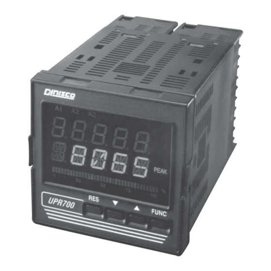
UPR700 Microprocessor-Based Pressure/Process Indicator Instruments with the suffix - A3 after the model number have the optional third alarm. PECIFICATIONS ECHANICAL PECIFICATIONS Case: Polycarbonate Black color Self-extinguishing degree VO according to UL 94 Front Panel: Designed and tested for 1P65 and NEMA 4X for indoor location... - Page 8 Installation Category: II ISPLAY PECIFICATION Display: LED technology, custom type. Upper Digits: Red color, 5 numeric digits, 7 segments with decimal point 13.2 mm high. Lower Digits: Green color, 5 alphanumeric digits (British flag), 14 segments with decimal points. 12.7 mm high. Bar Graph: Red color, 35 segment with 3% resolution.
- Page 9 UPR700 Microprocessor-Based Pressure/Process Indicator Input Impedance: <10 Ohm for linear current input >165 Kohm for linear voltage input Input Protection: Open circuit detection for strain gage (on signal and excitation wires) and 4-20 mA inputs; it is not available for 0-5 Vdc, 0-10 Vdc and 0-20 mA. Up or down scale keyboard programmable.
- Page 10 VDC and 0-20 MA). Up or down scale keyboard programmable. Input Impedance: >1 Mohm for thermocouple input. <10 Ohm for linear current input >165 Kohm T/C Lead Length: 100 Ohm max. Reference Junction Compensation: from -20 to 60°C. RTD Lead Length Compensation: up 20 Ohm/wire. Sampling Time: 1000 ms.
- Page 11 UPR700 Microprocessor-Based Pressure/Process Indicator the following functions: • alarm reset • remove zero calibration • peak reset • alarm, peak, and zero calibration • alarm and peak reset NOTE: This input is not isolated from primary input. A double or reinforced insulation between instrument output and power supply must be guaranteed by the external device.
- Page 12 Device Address: From 1 to 255 NOTE: The physical interface can only support up to 31 devices for each segment. Use multiple segments for more than 31 devices. Baud Rate: 600 up to 19200 baud. Format: 1 start bit, 8 bits with/without parity. 1 stop bit Parity: Even/Odd.
- Page 13 UPR700 Microprocessor-Based Pressure/Process Indicator 2.12 & S ECOND NALOG UTPUTS OMMON PECIFICATION Resolution: 0.1% of output span. Reference Accuracy: ±0.1% of output span @ 25 ± 10C and nominal line voltage. Linearity Error: <0.1% of output span. Output Noise: <0.1% of output span.
- Page 14 Fig. 2 Model UPR700 Outline Drawing...
-
Page 15: Unpacking
Depth behind panel: 5.04" (128mm) Weight: 1.43 lbs. (650g) ARDWARE The UPR700 is shipped with the hardware jumpers set for the following: Primary Input (Pressure) - Strain Gage Optional Secondary Input - Thermocouple Main Output - Voltage Optional Secondary Output - Voltage In addition the DIP switches controlling the software security lock codes are in the “OFF’... - Page 16 Fig. 3 UPR700 Wiring - 4-20mA Transmitter Internal 24 VDC Power Supply - Primary Input...
- Page 17 UPR700 Microprocessor-Based Pressure/Process Indicator Fig. 4 UPR700 Wiring - 4-20mA Transmitter Internal 24 VDC Power Supply - Secondary Input...
-
Page 18: Configurations
Please refer to Section 6.1 for the terminal assignments. Terminals are accessed by opening the terminal covers from the side with the “OPEN” legend. NOTE 1: The UPR700 is equipped with screw terminals, and no connectors are necessary when wiring the unit NOTE 2: When wiring the alarms, wire to the Common and NO (normally open) terminals to maintain a fail- safe configuration. - Page 19 UPR700 Microprocessor-Based Pressure/Process Indicator NOTE 3: Relay Outputs The contact rating of all outputs is equal to 2A/240 Vac on resistive load. • To avoid electrical shock, connect power line at the end of the wiring procedure. • For power connections use No 16 AWG or larger wires rated for at least 75°C.
- Page 20 ERMINAL SSIGNMENTS RTD or T/C+ RTD, T/C- or Linear - Secondary Input (Optional) Linear + or RTD compensation Strain Gage Signal + or Linear + Strain Gage Signal - or Linear - Calibration 2 Primary Input Excitation + Excitation -, Calibration 1 Main Output mA/V + Main Output mA/V - Remote Reset...
- Page 21 UPR700 Microprocessor-Based Pressure/Process Indicator µPR690 UPR700 W IRING ONVERSION ABLE µPR690 Terminal UPR700 Terminal Power 120 / 240 VAC Line Neutral Protective Ground Transducer Dynisco Cable Color Signal + Linear (+) Signal - Linear (-) Black Excitation (+) White Excitation (-)
-
Page 22: Operation
-1,000, and as high as 3,000 units. The standard UPR700 has 2 SPDT dry contact closure alarms, with an optional third alarm. In addition, it has one or two scalable analog retransmission outputs, or RS485 communications. - Page 23 The keys on the UPR700 must be pressed and released to move about in the configure screens. Do not press and hold a key unless told to do so; simply press the key and release it to advance to the next screen.
- Page 24 ARAMETERS The UPR700 parameters are grouped in five sections guarded by three security levels. The more common parameters are in the first groups, with the higher Group numbers for those parameters an operator would not normally modify.
- Page 25 UPR700 Microprocessor-Based Pressure/Process Indicator When the instrument is turned on, it will go through a self-test during which the front panel will illuminate. The instrument will then be in the normal display mode showing the value of the main input on the upper display, and the value of the secondary input on the lower display (if so equipped).
- Page 26 zero calibration, or it can reset both alarm and peak and perform remote zero calibration. To verify this parameter or to change it, press the FUNC key until nonE and GROUP show on the display. Press the key until 4 shows in the upper display. Press the FUNC key until the lower display shows LI.TYP.
- Page 27 TRAIN RANSDUCER If using a Dynisco transducer, the model number of the transducer will designate its own electrical output. For example, in plastic melt applications, the PT462E-5M-6/18 or TPT432A-10M-6/18 have a strain gage (0-3.33 mV/V dc full scale) signal output. Amplified units have a number where the strain gage units have a letter (E or A).
- Page 28 If you have an amplified transducer, or other amplified input, skip to Section 8.4.2. The UPR700’s default setting is strain gage input. To verify that the input is set for strain gage, press the FUNC key until nonE and GROUP show on the display. Press the key until 5 shows in the upper display.
- Page 29 The Dynisco strain gage transducers and amplified transmitters (if so equipped) have an internal shunt to allow the UPR700 to set the span full scale value automatically. To Access the Shunt Calibration parameter, press the FUNC key until nonE and GROUP show on the display. Press the key until 4 shows in the upper display.
- Page 30 8.4.3 S ETTING THE RIMARY NPUT YPE FOR AN MPLIFIED RANSMITTER If using a voltage or current output transducer, the model number of the transducer will designate its own electrical output. For example, a PT4624-7.5M-6/18 or an S840-000-10M has an amplified signal output.
- Page 31 UPR700 Microprocessor-Based Pressure/Process Indicator 8.4.4 S ETTING THE RIMARY NPUT CALE ALUE The model number of the transducer or transmitter will designate the full-scale pressure capability. For example, model number TPT432A-5M-6/18 indicates that the full-scale pressure is 5,000 (5M), while the PT150-5C indicates that the full-scale pressure is 500 (5C). Since the default value in the instrument is 10,000 full scale, the input full-scale value must be changed to 5,000 (or 500).
- Page 32 RESET key to go back to the active display. Remember to change the jumper settings to correspond to the proper input as shown in Figure 9 for board location and Figure 10 for input jumpers. Fig. 9 UPR700 Board Location...
- Page 33 UPR700 Microprocessor-Based Pressure/Process Indicator Fig. 10 Secondary Input Jumper Location...
- Page 34 8.5.2 S ETTING THE ECONDARY NPUT CALE AND ECIMAL OINT Skip to section 8.5.3 if the secondary input is for an RTD or a thermocouple. If the Instrument’s secondary input is set as a voltage or current, the Range Values need to be set. Press the FUNC key until nonE and GROUP show on the display.
- Page 35 UPR700 Microprocessor-Based Pressure/Process Indicator display. ETTING THE LARMS All Alarms supplied with the Instrument can be linked to either the Primary Input or the Secondary Input (if available), and are capable of being set as High Level Alarms or Low Level Alarms, and may operate in either Failsafe or Direct condition.
- Page 36 set point before it is enabled. Then it will work like a low alarm. This is ideal on startup. The default alarm type for Alarm 1 is high. To check or change this value press the FUNC key until nonE and GROUP show on the display. Press the key until 3 shows in the upper display.
- Page 37 In the event of an alarm condition or the loss of power to the UPR700, the relay will be de-energized and will then open. The same holds true for a NC contact. It will be held OPEN during normal operation. In the event of an alarm condition or the loss of power to the UPR700, the relay will be de-energized and will then close.
- Page 38 8.7.1 S ETTING THE NALOG UTPUT The Main Analog Output Type sets the output to specific voltages or currents. The available outputs are 0-20 mA, 4-20 mA, 0-10 VDC, -10 to +10 VDC, and 0-5 VDC. To change or view this value, press the FUNC key until nonE and GROUP show on the display.
- Page 39 UPR700 Microprocessor-Based Pressure/Process Indicator Fig. 11 Main Analog Output Jumper Location Fig. 12 Secondary Analog Output Jumper Location (optional)
- Page 40 8.7.5 S ETTING THE NALOG UTPUT ILTER Filtering is an electrical method of averaging the output values over a period of time to arrive at a smoother curve. This helps to eliminate short duration transients and spikes that may cause false or spurious readings.
- Page 41 UPR700 Microprocessor-Based Pressure/Process Indicator When the instrument is re-inserted into its case, the upper display will show CodE and the lower display will show UPR . 8.8.1 S ETTING THE ECURITY ODES FOR EVEL To view or change the security code, press the FUNC key and the lower display changes to CODE.A .
- Page 42 Be sure that the full scale and low scale values ( PI.FSV and PI.LSV ) have been set to match the range of the transducer and that the SHUNT function is ON and set to the correct percentage (80% for a typical Dynisco transducer). To calibrate the transducer to the instrument, press the FUNC key until nonE and GROUP show on the display.
- Page 43 UPR700 Microprocessor-Based Pressure/Process Indicator 9.1.3 C ALIBRATION OF RESSURE RANSDUCERS QUIPPED WITH XTERNAL HUNT ESISTORS Install the external shunt resistor across terminals 13 (signal -) and 14 (Cal 2). Be sure that the full scale and low scale values ( PI.FSV and PI.LSV ) have been set to match the range of the transducer and that the SHUNT function is ON and set to the correct percentage (as supplied by the transducer manufacturer.
- Page 44 upper display. Press the FUNC key and the upper display should show OFF while the lower display shows SHUNT . If the upper display does not show OFF , press the key until the upper display changes to OFF . Press the FUNC key to set the value and press RESET to return to the operating screen.
- Page 45 UPR700 Microprocessor-Based Pressure/Process Indicator Fig. 14 UPR700 Board Location 9.2.2 G ENERAL ALIBRATION ROCEDURE 1. Set the dip switches to calibration mode as shown above. The upper display should show CAL while the lower display shows UPR . 2. Use the keys to show the following functions: •...
- Page 46 5. If the values do not correspond with the values in the Calibration Parameters Summary Table below, use the keys to correct the value displayed. 6. When all the appropriate values are correct, set the dipswitches to operating mode. CALIBRATION PARAMETERS SUMMARY Parameter Circuit Input Type...
-
Page 47: Repair
The UPR700 is available with an RS485 Digital communications port. The configuration parameters for this option are found in the Group 3 parameters only if this option is included. The UPR700, when equipped with this option, is compatible with Modbus and J-Bus protocols, the choice of which is made in the Configuration/Setup menu. - Page 48 RROR ODES On power up, the UPR700 will enter a self-test mode to evaluate the condition of the equipment. If an error is detected, the screen will show an error code number in the upper display and the mnemonic Err , in the lower display.
- Page 49 When this is done return to normal operating mode. If the error persists, send the instrument to Dynisco for repair (See Section 13). Failure of RAM circuit. There is no correction; the device needs to be sent to Dynisco for repair (See Section 13).
- Page 50 4. To clean external plastic or rubber parts use only a cloth moistened with: • Ethyl Alcohol (pure or denatured) (C OH) or • Isopropyl Alcohol (pure or denatured) ([CH CHOH) or • Water (H • Always use the mildest means available. 5.
- Page 51 UPR700 Microprocessor-Based Pressure/Process Indicator IEC 1000-4-4: Electromagnetic compatibility (EMC) - Part 4: Testing and measurement techniques - Section 4: Electrical fast transient/burst immunity test ENV50141: Electromagnetic compatibility - Basic immunity standard - Conducted disturbances induced by radio-frequency fields - Immunity test...
- Page 52 Group 3 Function Sec. As Set SO.LNK Second Analog Range Link 8.7.2 SO.LO Second Output Range Low 8.7.3 SO.HI Second Output Range High 8.7.4 SC.ADR Serial Communication Interface Address 9.3.1 SC.BUS Protocol Type 9.3.2 SC.FRM Communication Type 9.3.3 SC.BDR Communication Baud Rate 9.3.4 DEFLT Loading Default Data...
- Page 53 UPR700 Microprocessor-Based Pressure/Process Indicator SECURITY - Group 1 Available: Only if CODE.A or CODE.B or CODE.C are On. Upper display: A b C or A b C. or A b. C or A. b. C. One or more letters followed by a decimal point means that the access to modification of the parameters of the related security level is inhibited.
- Page 54 Lower display: DEFLT Range: keys to switch the upper display from OFF to On 1, the press FUNC key to load the default data of the parameters belonging to Group 1. GROUP ACCESS NUMBER Available: Always Upper display: OFF Lower display: GROUP Range: keys to switch the upper display from nonE to 1, 2, 3, 4 or 5 and then gain access to the parameters of the selected group by pressing the FUNC key.
- Page 55 UPR700 Microprocessor-Based Pressure/Process Indicator Upper display: Time constant of the alarm 1 filter. Lower display: A1.FL Range: OFF, 0.4, 1, 2, 3, 4, 5 sec. Default value: 0.4 sec. ALARM 2 FILTER - Group 2 Available: Only if A2.LNK is different than OFF.
- Page 56 12.3 ROUP EFAULT ARAMETERS PRIMARY INPUT FULL SCALE VALUE - Group 3 Available: Always Upper display: Full scale value Lower display: PI.FSV Range: from 10 to 99950. Changes to this value affect the values for the pressure input low scale, the alarm set points and the retransmission limits. Default value: 10000.
- Page 57 UPR700 Microprocessor-Based Pressure/Process Indicator SECONDARY INPUT RANGE LOW - Group 3 Available: Only if SI.TYP is 0-20, 4-20 or 0-10. Upper display: Secondary input range low. Lower display: SI.LO Range: from -1000 to 3000. Default value: SECONDARY INPUT RANGE HIGH - Group 3 Available: Only if SI.TYP is 0-20, 4-20 or 0-10.
- Page 58 Range: OFF, PrI.In, SEc.In. Disabled, primary input, secondary input. Default value: Primary input. ALARM 2 TYPE - Group 3 Available: Only if A2.LNK is different than OFF. Upper display: Selection of alarm 2 type. Lower display: A2.TYP Range: HI, LO, InhIb. High, low, low with mask start-up Default value: High.
- Page 59 UPR700 Microprocessor-Based Pressure/Process Indicator MAIN ANALOG OUTPUT RANGE HIGH - Group 3 Available: Only if MO.TYP is different than OFF. Upper display: Range high for main analog output. Lower display: MO.HI Range: from 0 to PI.FSV (if PO.LNK = PrI.In) from -1000 to 3000 (if PO.LNK - SEc.In).
- Page 60 Range: nodbS, JbuS. Modbus/Jbus selection. Default value: Modbus. COMMUNICATION TYPE - Group 3 Available: Only if SC.ADR is different than Off. Upper display: Number of bits. Lower display: SC.FRM Range: 8, 8 E, 8 O. 8 bit without parity, 8 bit + even parity, 8 bit + odd parity. Default value: 8 bit without parity.
- Page 61 UPR700 Microprocessor-Based Pressure/Process Indicator PRIMARY INPUT FAIL SAFE - Group 4 Available: Always. Upper display: Primary input fail safe condition. Lower display: PI.IFS Range: HI, LO. Default value: High. SECONDARY INPUT FAIL SAFE - Group 4 Available: Only if SI.TYP is different than OFF.
- Page 62 Range: From 0.1 to 10.0% of the selected range. Default value: 1.0% ALARM 2 RESET MODE - Group 4 Available: Only if A2.LNK is different than OFF. Upper display: Selected reset mode for alarm 2. Lower display: A2.RES Range: Auto, LAtCh. Automatic reset, manual reset Default value: Auto.
- Page 63 UPR700 Microprocessor-Based Pressure/Process Indicator LOGIC INPUT CONFIGURATION - Group 4 Available: Always. Upper display: Configuration of logic input. Lower display: LI.TYP Range: OFF, AL, P, AL-P, CAL.0, ALL. Disabled, alarm reset, peak reset, alarm and peak reset, zero calibration, alarm, peak reset, zero cal/all Default value: Alarm and peak reset.
- Page 64 12.5 ROUP EFAULT ARAMETERS PRIMARY INPUT SELECTION - Group 5 Available: Always. Upper display: Type of primary input selection. Lower display: PI.TYP Range: Str, 0-20, 4-20, 0-5, 0-10. Strain gage, 0-20 mA, 4-20 mA, 0-5V, 0-10V. Default value: Strain gage. NOTE: Remember to make the proper selection on the hardware jumpers.
- Page 65 UPR700 Microprocessor-Based Pressure/Process Indicator LOADING DEFAULT DATA - Group 5 Available: Only if access to level C is allowed. Upper display: OFF Lower display: DEFLT Range: keys to switch the upper display from OFF to On 5, then press FUNC key to load the default data of the parameters belonging to group 1, group 2, group 3, group 4 and group 5.
- Page 66 For technical assistance please call 800-221-2201 or 508-541-9400 or fax 508-541-9436. ARRANTY This Dynisco product is warranted under terms and conditions set forth in the Dynisco Web Pages. Go to www.dynisco.com and click on “Warranty” at the bottom of any page for complete details.
- Page 67 OTES...
- Page 68 OTES...
-
Page 69: Warranty Registration Card
CITY _____________________________ STATE _____________ ZIP __________________ COUNTRY _____________________________________________________________________ TELEPHONE _____________________________ FAX ________________________________ My application is _______________________________________________________________ Is this your first purchase from Dynisco? YES __________ NO __________ How did you first hear of Dynisco? ADVERTISING ________ REP __________ PREVIOUS USE ___________ COLLEAGUE _____________ DIRECTORY ______________... - Page 70 Place Stamp Here DYNISCO LLC 38 FORGE PARKWAY FRANKLIN, MA 02038 ATTN: MARKETING DEPT.
- Page 72 Visit us on the world wide web: DyniscoLLC 38 Forge Parkway Dynisco UK Ltd. Franklin, MA 02038 Silver Birches Business Park Aston Road, Bromsgrove Worcestershire B60 3EU Tel: +1 508 541 9400 Great Britain Fax: +1 508 541 9436 Email: InfoInst@dynisco.com...
Need help?
Do you have a question about the UPR700 and is the answer not in the manual?
Questions and answers