Table of Contents
Advertisement
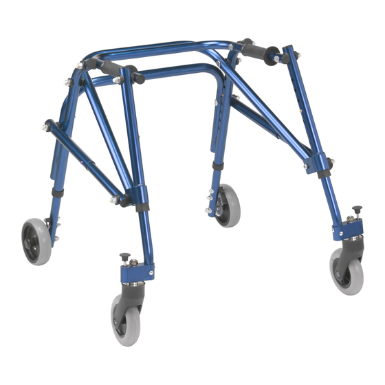
Nimbo Lightweight Posterior
Posture Walker
Assembly & Operating Instructions
with optional Forearm Platforms
with optional Pelvic Stabiliser
Please read these instructions carefully before assembling or operating this product.
Ensure you are familiar with all of the safety and operating instructions.
Advertisement
Table of Contents

Related Manuals for Drive Medical Nimbo

Summary of Contents for Drive Medical Nimbo
- Page 1 Nimbo Lightweight Posterior Posture Walker Assembly & Operating Instructions with optional Forearm Platforms with optional Pelvic Stabiliser Please read these instructions carefully before assembling or operating this product. Ensure you are familiar with all of the safety and operating instructions.
-
Page 2: Specifications
Back Introduction The Nimbo Walking Aid is available in five different sizes. It is used as a posterior walker and is available with a number of accessories. The Nimbo may be used outdoors but is restricted to smooth and even terrain without obstacles. -
Page 3: Important Safety Information
• Pay attention to the environment and avoid obstacles, bad flooring or carpet and other hazards. • Ensure that only Drive parts are used on the Nimbo. Periodically visually inspect the walker for signs of wear. • Please ensure that only one person uses the walker at any one time, and do not exceed the weight limit. -
Page 4: Optional Accessories
Parts Nimbo Walker Front Swivel Wheels (pair) Nimbo Frame Rear Anti-reverse Wheels (pair) Optional Accessories Forearm Platform Outdoor Wheels Pelvic Stabiliser Handgrips (pair) Outdoor Wheels (x 2) Pelvic Stabiliser Armrests (pair) Washers (x 2) Armrest Supports (x 2) Fixing Bolts (x 2) Tools Required: 10mm and 13mm spanner, 6mm Allen key. - Page 5 1-4. To open up the Nimbo: lay the frame on the ground with the front legs (1 & 2) on top (a). While holding the back legs (3 & 4) pull up on the front legs 1 & 2 (b). When both legs are fully extended (c) you should hear a ‘click’...
- Page 6 Assembly ‘Click’ Step 2 Each wheel is marked with a number 1 - 4, to match the numbers on the frame. To fit the wheels: fit the first wheel (1) by pushing into the frame at position 1. Push in until the button pops out of one of the holes. Repeat for the other front wheel 2. Tip: You might need to rotate the tube slightly until the button pops out.
- Page 7 Assembly Step 4 Lift up the frame and position onto its wheels. The front and the back wheels have 9 height positions. To adjust the height: press in the button (arrow) and move the wheel to the required hole position. Make sure that the button pops into position in the frame, you should hear a ‘click’.
- Page 8 Assembly Retaining clip Step 6 OPTIONAL The back wheels can be locked to stop the chair from rolling backwards. To lock the back wheels: release the metal pins from the plastic retaining clips. Let the pins fall into position onto the teeth on the wheels. To unlock the wheels, move the pins back into the plastic clips.
- Page 9 Fitting the Forearm Platform Hand rail Step 1 Removing the hand grips: the hand grips are factory fitted and are a tight fit they will need to be cut off using a sharp knife before the forearm platform can be fitted. Carefully using a sharp knife make a cut along the hand grip, peel back the grip and remove from the hand rail.
- Page 10 Fitting the Forearm Platform - continued Spacer Knob Lever Step 3 Step 4 Bolt on the armrest. The armrest comes Slide in the handgrips to the required with 2 spacers for lateral adjustment, position and tighten using the knob on these should fit between the armrest and the underside.
- Page 11 Fitting the Pelvic Stabiliser Hand grip tube Washers & fixing bolts Step 1 Step 2 Position the pelvic stabiliser up under the Line up the holes and attach from behind back of the hand grip tube as shown. using the washers and fixing bolts, only hand tighten the fixing bolts.
-
Page 12: Warranty
2. To apply the warranty should your Drive Nimbo require attention please contact the your Drive Medical dealer / service agent. 3. Should any part of the Drive Nimbo require repair or full or part replacement as a result of a manufacturing or material defect within 24 months of receiving the Nimbo, parts will be supplied free of charge.
Need help?
Do you have a question about the Nimbo and is the answer not in the manual?
Questions and answers