Table of Contents
Advertisement
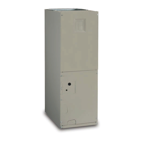
B6BM, B6EM, & B6VM SERIES
INStALLAtIoN INStRuctIoNS
AIR HANDLER
It is your responsibility to know this product better than your customer. this includes being
able to install the product according to strict safety guidelines and instructing the customer on
how to operate and maintain the equipment for the life of the product. Safety should always be
the deciding factor when installing this product and using common sense plays an important
role as well. Pay attention to all safety warnings and any other special notes highlighted in the
manual. Improper installation of the furnace or failure to follow safety warnings could result in
serious injury, death, or property damage.
these instructions are primarily intended to assist qualified individuals experienced in the proper
installation of this appliance. Some local codes require licensed installation/service personnel
for this type of equipment. Please read all instructions carefully before starting the installation.
Return these instructions to the customer's package for future reference.
Do Not DEStRoY. PLEASE READ cAREFuLLY & KEEP IN A SAFE PLAcE FoR FutuRE REFERENcE.
IMPoRtANt
AttENtIoN INStALLERS:
Advertisement
Table of Contents

Related Manuals for Maytag B6BM series


Summary of Contents for Maytag B6BM series
- Page 1 B6BM, B6EM, & B6VM SERIES INStALLAtIoN INStRuctIoNS AIR HANDLER IMPoRtANt AttENtIoN INStALLERS: It is your responsibility to know this product better than your customer. this includes being able to install the product according to strict safety guidelines and instructing the customer on how to operate and maintain the equipment for the life of the product.
-
Page 2: Table Of Contents
tABLE oF coNtENtS IMPoRtANt SAFEtY INFoRMAtIoN ......3 StARtuP & ADjuStMENtS ........13 Before You Start the Unit ..........13 REquIREMENtS & coDES ......... 3 Refrigerant Charging ........... 13 Air Circulation .............. 14 GENERAL INFoRMAtIoN ..........4 Running the Blower Continuously ......14 Before You Install this Unit ........... -
Page 3: Important Safety Information
IMPoRtANt SAFEtY INFoRMAtIoN REquIREMENtS & coDES INSTALLER: Please read all instructions before servicing this equipment. Pay attention to all safety warnings and wARNING: any other special notes highlighted in the manual. Safety markings are used frequently throughout this manual to this unit must be installed in accordance designate a degree or level of seriousness and should not with instructions outlined in this manual... -
Page 4: General Information
GENERAL INFoRMAtIoN operation of Air Handler During construction This appliance has been tested for capacity and efficiency cAutIoN: in accordance with AHRI Standards and will provide many years of safe and dependable comfort, providing it is properly installed and maintained. Abuse, improper use, and/or Failure to follow these instructions will void the improper maintenance can shorten the life of the appliance factory warranty and may significantly reduce... -
Page 5: Installation In A Garage
• Before occupying the structure: The filter must be replaced practice as specified in the ASHRAE recommendations or cleaned, the duct work must be inspected and cleaned for duct transitions. of any construction debris, and the air handler must be •... -
Page 6: Air Handler Installation
AIR HANDLER INStALLAtIoN B6 series air handler’s are shipped ready for vertical upflow installation and are approved for attic, basement, alcove/ closet or crawlspace installation with zero clearance to combustibles. See Table 1, (page 4) for required installation clearances. this appliance is approved only for indoor use. -
Page 7: Horizontal Left Installations
to avoid damage to the ceiling in the event of condensate 7. Insert the plug (from horizontal drain pan) into the open overflow. Additionally, it is recommended that an approved and unused drain hole in the drain pan at the bottom of water level indicator or float switch device be used to shut the unit to block bypass air. -
Page 8: Refrigerant Line Connections
Refrigerant Line connections • If leakage is found, clearly mark the location of the leak and return the coil to the distributor for processing. wARNING: • If no leaks are found, the coil may be installed. 3. Depress the valve to relieve all pressure from the coil. 4. -
Page 9: Condensate Drainage
4. Position grommet on line set with sufficient distance away from brazing area. Brazing processes can permanently damage grommets. 5. Connect the suction and liquid lineset tubes. cAutIoN: It is recommended that a wet rag be wrapped around the suction line in front of the close off plate or the sensing bulb (if tXV is installed) before applying heat. -
Page 10: Electrical Connections
ELEctRIcAL coNNEctIoNS restricted. As an alternative to a separate drain line, an approved water level indicator or float switch device may wARNING: be used to shut down the unit in the event water is detected in the auxiliary pan. • Install a single 5 inch trap in the condensate drain line as ELEctRIcAL SHocK, FIRE oR close to the coil as possible. -
Page 11: Grounding
control Board • If replacing any of the original wires supplied with the unit, the replacement wire must be copper wire consisting of The control board in the air handler controls the timing the same gauge and temperature rating. sequence of the elements. The board is equipped with a 3 •... - Page 12 Thermostat Thermostat Thermostat NOTE: Jumper W1 & W2 together if not using W2 on thermostat Conditioner Handler Conditioner Conditioner Y/Y2 Y/Y2 Handler Handler Typical Air Conditioner with Typical Air Conditioner with Typical 2-Stage Air Conditioner Standard Air Handler 2-Stage Air Handler with 2-Stage Air Handler Thermostat Thermostat...
-
Page 13: Twinning
twINNING StARtuP & ADjuStMENtS These instructions are to be used when connecting two B5 or Before You Start the unit B6 air handlers (2-5 ton models) to a common single stage Prior to start-up, complete the following inspections: A/C condensing unit or heat pump. Twinning is possible for √... -
Page 14: Air Circulation
Air circulation Blower configurations Running the Blower Continuously Determining Nominal System Capacity Set the thermostat’s system mode to oFF and the thermostat’s To select the appropriate airflows for the air handler, the fan mode to oN. The blower motor should run continuously. nominal system capacity must be known. -
Page 15: Selecting Basic Heating Airflow
(see page 11). During normal operation, the motor will 1. If the room thermostat incorporates a humidity sensor and DHuM output, connect the DHuM on the thermostat to gradually change speeds during start-up, shut down, when the DHuM terminal on the motor control board. thermostat inputs change, and when the duct static pressure 2. -
Page 16: Troubleshooting
tRouBLESHootING cABINEt SIZE FILtER SIZE If the air handler fails to operate, check the following: 12 x 20 x 1 • Is the electric turned on? 18 x 20 x 1 • Is the thermostat operating properly? • Are the blower compartment door(s) in place? 20 x 20 x 1 •... -
Page 17: Figures & Tables
FIGuRES & tABLES 3/4” 3/4” 3/4” 13” 11/8” K.O. (typ.) “A” 1 7/8" K.O. 11/4” 15/8” 11/4” 17/8” 3 1/4” 2 5/8” 1 1/8” 1 7/8” 7/8" K.O. 11/8” K.O. (typ.) 1 7/8” 3 5/8” 5 5/8” 13/4” K.O. (typ.) DETAIL “D”... - Page 18 Circuit Breaker (60A) Heating Element Assembly Transformer Motor Control Board Blower Control Upper Door Wheel Board Assembly Capacitor Motor Mount Kit Blower Housing Blower Coil Motor Assembly Filter Door Horizontal Vertical Drain Pan Drain Pan Filter Tracks Lower Door Assembly Air Handler components Figure 14.
-
Page 19: Airflow Data
Airflow Data DRY coIL ESP 0.10 0.20 0.30 0.40 0.50 0.60 0.70 0.80 Corrected ESP 0.00 0.07 0.19 0.30 0.42 0.53 0.65 0.76 Medium *24K A-cABINEt Corrected ESP 0.00 0.00 0.11 0.23 0.36 0.48 0.60 0.72 High 1072 1026 Corrected ESP 0.00 0.00 0.00... - Page 20 cooLING oR HEAtING AIRFLow (cFM) SwItcH SEttINGS 0 = oFF, 1 = oN DRY coIL ESP — — 1030 B6EM 1115 1085 1060 1020 A-cABINEt 1155 1130 1095 1070 1040 1010 1200 1175 1145 1110 1085 1060 1025 1000 1240 1215 1195 1170...
-
Page 21: Settings (Cfm)
NoMINAL ELEctIc HEAt Kw cABINEt 1000 1300 1000 1050 1100 1300 1500 1000 1100 1150 1200 1400 1600 1800 2000 NotE: SeeTable 6, (page 20) for appropriate switch settings for these airflows. B6EM (FSHE) Minimum Heating Airflow Settings (cFM) table 7. A-cABINEt SwItcH SEttINGS NoMINAL... - Page 22 cooLING AIRFLow HEAtING AIRFLow cooL SwItcH SEttING A/B SwItcH SEttING AIRFLow A/B SwItcH SEttING HEAtER KIt AIRFLow 0 = oFF, 1 = oN 0 = oFF, 1 = oN (cFM) 0 = oFF, 1 = oN INStALLED (Kw) (cFM) 1000 1000 1300 B6VM...
-
Page 23: Electrical Diagrams
Electrical Diagrams 3A Fuse BLWDTC BLWDTC_R COOL HEAT LED 1 HEATER P1 Single Stage control Board Figure 15. LED 1 HEATER P1 two - Stage control Board Figure 16. - Page 24 TEST PORT EXPANSION PORT FAN SPEED 1 2 3 4 5 6 7 8 COOL HEAT STATUS BLOWER MOTOR Fixed Speed Motor control Board Figure 17. STATUS LIGHTS L2-IN L2-OUT Y/Y2 L1-IN L1-OUT DEHUM FAN SPEED 2 3 4 5 6 7 8 TEST PORT COOL HEAT...
- Page 25 WIRING DIAGRAM Air Handler Remarques NOTES: 1. Le connecteur de vitesse du moteur du ventilateur peut 1. The blower motor speed tapconnection may not be as shown. différer de l’illustration. Consultez les Instructions See the Installation Instructions. d’installation. 2. Disconnect all power beforeservicing. 2.
- Page 26 WIRING DIAGRAM Air Handler with Fixed Speed High Efficiency Motor Remarques NOTES: 1. Le connecteur de vitesse du moteur du ventilateur 1. The blower motor speed tap connection may not be peut différer de l’illustration. Consultez les as shown. See the Installation Instructions. Instructions d’installation.
- Page 27 WIRING DIAGRAM Air Handler with Variable Speed High Efficiency Motor Remarques 1. Le connecteur de vitesse du moteur du ventilateur peut NOTES: différer 1. The blower motor speed tap connection may not be as shown. de l’illustration. Consultez les Instructions d’installation. See the Installation Instructions.
-
Page 28: Electrical Data
Electrical Data B6BM MINIMuM cIRcuIt AMPAcItY & MAXIMuM oVERcuRRENt PRotEctIoN 240 VAc, 50 & 60 HZ, SINGLE PHASE 208 VAc, 50 & 60 HZ, SINGLE PHASE HEAt KIt MoDEL cABINEt cAPAcItY NuMBER H6HK- NONE 005H-XX 26.6 26.6 23.3 23.3 008H-XX 41.2 41.2 35.9... - Page 29 B6(E,V)M MINIMuM cIRcuIt AMPAcItY & MAXIMuM oVERcuRRENt PRotEctIoN 240 VAc, 50 & 60 HZ, SINGLE PHASE 208 VAc, 50 & 60 HZ, SINGLE PHASE HEAt KIt MoDEL cABINEt cAPAcItY NuMBER H6HK- NONE 005H-XX 29.5 29.5 26.4 26.4 008H-XX 44.1 44.1 39.1 39.1 010H-XX...
- Page 30 coNtRoL SIGNAL & MoDE oPERAtIoN totAL Kw BoARD ActIoN tage eat on instantly 5 KW eat blower on aFter seCond delay tage eat on instantly 10 KW eat blower on aFter seCond delay tage eat on aFter seConds delay tage eat on instantly eat blower on aFter seCond delay...
- Page 31 coNtRoL SIGNAL & MoDE oPERAtIoN totAL Kw BoARD ActIoN tage eat on instantly 5 KW ool blower on aFter seCond delay tage eat on instantly 10 KW ool blower on aFter seCond delay tage eat on aFter seConds delay tage eat on instantly ool blower on aFter seCond delay...
-
Page 32: Installation / Performance Check List
INStALLAtIoN / PERFoRMANcE cHEcK LISt INStALLER NAME: ATTENTION INSTALLERS: It is your responsibility to know this product better than your customer. This includes being able to install the product according to strict CITY: STATE: safety guidelines and instructing the customer on how to operate and maintain the equipment for the life of the product.