Advertisement
OWNER'S MANUAL
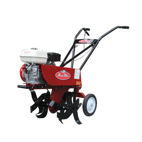
International Merry Tiller
Model IT950IC
CAUTION:
Before using this product, read this
manual and follow all Safety Rules and
Operating Instructions.
MACKISSIC, INC. P.O. BOX 111, PARKER FORD, PA 19457-0111
PHONE: (610) 495-7181
e-mail: info@mackissic.com
FAX: (610) 495-5951
www.mackissic.com
P/N 710-3402
12/22/16
Advertisement
Table of Contents

Related Manuals for Merry Tiller IT950IC


Summary of Contents for Merry Tiller IT950IC
- Page 1 OWNER’S MANUAL International Merry Tiller Model IT950IC CAUTION: Before using this product, read this manual and follow all Safety Rules and Operating Instructions. MACKISSIC, INC. P.O. BOX 111, PARKER FORD, PA 19457-0111 PHONE: (610) 495-7181 e-mail: info@mackissic.com FAX: (610) 495-5951 www.mackissic.com...
-
Page 2: Table Of Contents
Transmission Assembly Drawing ..Tiller Drawing ........Handle Bar Drawing ......Warranty .......... MERRY TILLER ACCESSORIES AVAILABLE WHEREVER MERRY TILLER PRODUCTS ARE SOLD MT-951 Finger Tine Assemblies - Right and Left Inside MT-952 Finger Tine Assemblies - Right and Left Outside... -
Page 3: Safety
SECTION I - SAFETY This symbol points out important safety instructions which, if not followed, could endanger the personal safety and/or property of yourself and others. Read and follow all instructions in this manual before attempting to operate your tiller. Failure to comply with these instructions may result in personal injury. - Page 4 OPERATORS INSTRUCTIONS STARTING: 1. Remove or rotate wheels to up position. 2. Adjust drag bar for desired depth. 3. Stand between handlebars. 4. Allow clutch lever to drop into disengaged position. 5. Move throttle lever to run position. 6. Reach forward to set choke lever to choke position.
-
Page 5: General Preparation
GENERAL PREPARATION Read the owner’s manual carefully and in its Disengage clutch before starting the engine entirety before attempting to assemble this (motor). machine. Be thoroughly familiar with the Never attempt to make any adjustments while controls and the proper use of the equipment the engine (motor) is running (except where before operation. -
Page 6: Repair And Maintenance Safety
REPAIR AND MAINTENANCE SAFETY Use extreme care in handling gasoline and other Check the belt and engine mounting screws at fuels. They are extremely flammable and the frequent intervals for proper tightness. Also vapors are explosive. visually inspect tines for wear or damage. Use ... -
Page 7: Assembly Instructions
SECTION II - ASSEMBLY INSTRUCTIONS PACKAGE CONTENTS POLYBAG BOLT BAG OWNER’S MANUAL TILLER 1 EA CLUTCH SPRING 1 EA 1/4-20 X 2 1/2 EYEBOLT HANDLE BARS (2) ENGINE MANUAL 1 EA PULL CORD HOLDER 4 EA 1/4-20 NYLOCK NUT ... - Page 8 STEP III - Attaching the Throttle Control Cable, Clutch Cable and Starter Rope 1. Insert throttle control (item #52, pg. 20) through cable guide (item #50, pg. 20). Attach throttle control to handlebar with 2 ea. 10-32 x 1 ¼” machine screw (item #33, pg. 20) and 2 ea. 10-32 Kep nut (item #32, pg. 20). 2.
-
Page 9: Lubrication & Engine Start Up
SECTION III - LUBRICATION & ENGINE START UP FOR INFORMATION ABOUT: FUEL STARTING STOPPING RECOMMENDED MAINTENANCE SERVICE STORAGE ENGINE WARRANTY INFORMATION REFER TO THE ENGINE OWNER’S MANUAL. THE ENGINE ON YOUR INTERNATIONAL TILLER HAS BEEN SHIPPED DRY. BE SURE TO SERVICE THE ENGINE ACCORDING TO THE ENGINE OWNER’S MANUAL PRIOR TO STARTING. -
Page 10: Operation
SECTION IV - OPERATION TILLING The International Tiller is equipped with a set of rear wheels. These wheels are designed only for transporting the tiller to and from the tilling area. They should never be used during the tilling process. When tilling, the wheels should be removed or rotated into the up position and the drag bar should be set to till at the desired depth. - Page 11 OPERATION: 1. NEVER allow bystanders near the unit. 2. DO NOT put hands or feet near or under rotating parts. 3. Exercise extreme caution when operating on or crossing gravel drives, walks, or roads. Stay alert for hidden hazards of traffic. DO NOT carry passengers. 4.
-
Page 12: Service - Maintenance - Repair
SECTION V - SERVICE - MAINTENANCE - REPAIR The transmission has been factory serviced with “00” grease. No additional lubrication is necessary or recommended. Belt tension should be checked, and adjusted if necessary, after initial 20 to 30 minutes of operation. Follow directions below. Belt and Clutch Adjustment CAUTION: DO NOT ADJUST BELT OR CLUTCH WITH THE ENGINE RUNNING! ... -
Page 13: Service Notes
When it is necessary to make internal repairs to the transmission, it is advisable to take your tiller to an authorized MERRY TILLER dealer, especially if there are signs of excessive wear. Following are some suggestions that will help to determine the amount of wear. - Page 14 The inner seal faces into the transmission and is designed to keep lubricant from escaping from the transmission. The outer seal faces outward and is designed to keep dirt out of the transmission. The Merry Tiller transmission is lubricated with heavy “00” grease. If the seals fail, it may not be noticed due to the heavy consistency of the grease.
-
Page 15: Storage
SECTION VI - STORAGE Clean the tiller thoroughly. Wipe down the tiller with an oiled rag to prevent rust ( use a light oil or silicone). Store the unit in a clean, dry area. Do not store next to corrosive material, such as fertilizer. NOTE: If storing in an unventilated or metal storage shed, rustproof the equipment by coating with a light oil or silicone. - Page 17 710-2281 TRANSMISSION ASSEMBLY ITEM NO. PART NO. DESCRIPTION QTY. 710-1885 L.H. Case Half Assembly (include 1A to 1D) 706-0343 Tine Shaft Bearing 706-0344 Oil Seal 706-0345 Bearing 706-0342 Drive Shaft Seal 710-1886 R.H. Case Half Assembly (includes items 2A to 2D) 020-0014 Soft Plug 706-0343...
- Page 19 INTERNATIONAL PARTS LIST ITEM PART NO. DESCRIPTION QTY. 710-2281 Transmission Assembly 030-0622 IT950IC Engine 706-0137 Adjustment Link 5/16” Split Lockwasher 090-0394 5/16-18 x 1-1/4” HHCS, GR5 090-0089 5/16/18 x 1-3/4” HHCS, GR5 090-0091 5/16-18 x 1” HHCS, GR5 090-0088 710-1854 Engine mount spacer 5/16-18 x 3”...
- Page 20 PARTS LIST FOR HANDLE ASSEMBLY ITEM NO. PART NO. DESCRIPTION QTY. 090-0470 1/4-20 Nylock Nut 090-0091 5/16-18 x 1 3/4 HHCS 090-0233 5/16 Flat Washer 706-1826 Cross Brace 710-3406 R.H. Tie Brace 710-3405 L.H. Tie Brace (Not Shown) 706-2637 R.H. Handle Assembly (includes item 31C) 706-3254 Clutch Control Lever 706-0630...
-
Page 22: Warranty
LIMITED WARRANTY Any product manufactured by MacKissic, Inc. and found, in the judgment of MacKissic, Inc., to be defective in material or workmanship, will be repaired or replaced by an Authorized MacKissic Service Dealer without charge for parts and labor to the original owner of the MacKissic product. The MacKissic product including any defective part must be returned to an Authorized MacKissic Service Dealer within the warranty period.
Need help?
Do you have a question about the IT950IC and is the answer not in the manual?
Questions and answers