
Summary of Contents for Balboa Lite-Leader Series
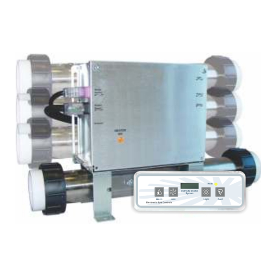
- Page 1 SpaDepot.com CS7100B-F SERIES Operation Manual Covers the following CS series: 7100B-F, 7109B-F 7100B-4.0-F, 7109B-4.0-F ® BALBOA LITE-LEADER Series...
- Page 2 Introduction This manual covers electrical and installation details on the following product series. Some photos and instructions may not apply to the product you have purchased. -U Series "Fixed" Heater configuration: This series is designed to fit the most common heater position. Depending upon the actual control being replaced, you may still need to modify the plumbing to achieve proper alignment.
-
Page 3: Table Of Contents
Contents Important Safety Instructions.......3-4 Electrical Installation..........5-7 GFCI Wiring Detail..........7 Heater Installation...........8 Plumbing Considerations........9 Temperature Sensor Installation......9 Temperature Sensor Connections......10 Optional Heaters...........10 Optional Cords............10 Power Connection..........11 Cord Connections..........12 System Plug Pinouts..........12 Spa Light...............12 Equipment Connections........13 Circuit Board Configurations.........14 System Start-Up............15 Filtration Cycles.............15 Spa Side Control Operation........16 Operational Considerations........17... -
Page 4: Important Safety Instructions
IMPORTANT SAFETY INSTRUCTIONS DANGER To reduce the risk of injury, do not permit children to use this product unless they are closely supervised at all times. WARNING - RISK OF CHILD DROWNING. Extreme caution must be exercised to prevent unauthorized access by children. To avoid accidents, ensure that children cannot use a spa or hot tub unless they are supervised at all times. - Page 5 Persons using medication should consult a physician before using a spa or hot tub since some medication may affect heart rate, blood pressure, and circulation. For Cord and Plug Connected Units Must be connected to a grounded, grounding type receptacle only. NEVER connect the spa to an extension cord.
-
Page 6: Electrical Installation
Electrical Installation A licensed electrician must accomplish the electrical installation in accordance with the National Electric Code(NEC) Article 680, and any local codes in effect at the time of installation. Refer to the System Data Label for equipment voltage and maximum amperage draws. - Page 7 Electrical Installation ELECTRICAL CONNECTIONS OPTION 1 GFCI Installed in Main Service Panel MAIN BREAKER PANEL INLINE SPA DISCONNECT PORTABLE SPA LINE 1 LINE 2 REFER TO GFCI WIRING DETAIL ON PAGE 8 Option 1 shows the power from GFCI breaker installed into main service panel to a service disconnect within line-of-site of the spa.
-
Page 8: Gfci Wiring Detail
Electrical Installation If your system was configured to include a 120VAC power cord, ensure that the proper receptacle has been installed (a dedicated circuit is required). DO NOT under any circumstances modify a 20 Amp plug to fit into a 15 Amp receptacle or use an extension cord. -
Page 9: Heater Installation
Heater Installation The Lite-Leader Series Fixed Heater and "US" Series Slide Heater systems will arrive from the factory with the heater mounted in the bottom location as pictured in Step 1. The "US" Series Slide Heater can be installed and used in this configuration or you can move the Slide Heater to the back of the control as shown below to align easily with your particular plumbing arrangement. -
Page 10: Plumbing Considerations
10’ x 3/8” temperature sensor to replace the existing temperature sensor for “Drywell” applications. Option #3 Using your existing sensors: If you are replacing an existing Balboa Lite Leader system, you may use your existing sensors. This will be optional in applications with the temperature sensor installed in a “Wetwell”... -
Page 11: Temperature Sensor Connections
Temperature Sensor Connections Pressure Switch High-Limit Temp Sensor 1/4” Bulb 3/8” or 1/4” Bulb It is important to connect the sensor(s) to the correct position(s) on the PCB. Please refer to the photo above for the correct connection points. The Hydro-Quip Lite-Leader sensor kit has been developed to offer the maximum in flexibility. -
Page 12: Power Connection
Power Connection Use the illustrations and instructions below to connect your input power wiring. Always refer to the wiring diagram provided with your control (located inside the hinged cover) prior to connecting any wires. 120-Volt Blue & White Neutral Wires Crimped Together BLUE NEUTRAL WHITE... -
Page 13: Cord Connections
Cord Connections 2-SPEED PUMP CORD CONFIGURATION The following wiring configuration is for two-speed pump circuits. Black = Low Speed Red = High Speed System Pump White = Common Green = Ground OZONE CORD CONFIGURATION The following wiring configuration is for a ozone . Black = Hot/Line Black = Hot/Line Ozone... -
Page 14: Equipment Connections
Equipment Connections Voltage Conversions - All equipment circuits in this control system are convertible from 120v to 240v. Pump 1 is a two-speed pump utilizing the black wire for low speed and the red wire for high speed. Pump 1 is factory configured for 120V. To convert pump 1 to 240V, move the red coded white wire (Common) from N to L2. -
Page 15: Circuit Board Configurations
Circuit Board Configurations Jumper J23 - 50 amp (high amp mode) / 20 amp (low amp mode). 50 amp 20 amp (default) J23 50A / 20A J23 50A / 20A Connector J1 - Spaside plug. Connector J20 - High Limit and Temperature sensor plug. While looking at the board in the above orientation, the high limit plugs in to the left side of the connector and the temperature sensor plugs in to the right side of the connector. -
Page 16: System Start-Up
System Start-Up 1) Unplug the power cord (120-volt system only) or turn the electrical power “OFF” at the service or breaker panel (120 or 240 volt permanently connected units.) 2) Open all WATER shut-off valves. 3) For spas equipped with a hose bib or drain valve, make sure that it has been closed. 4) For spas equipped with in-line or pressure water filters, make sure that the filter nut, housing drain plug, and air relief valve are closed and tight. -
Page 17: Spa Side Control Operation
Operation Considerations The following describes situations you may encounter and situations to be aware of. Warm Weather Conditions Since your spa will normally be expected to maintain warm to hot water ready for use, a great deal of attention has been directed to the energy conservation detail of insulation to keep electrical cost down. -
Page 18: Operational Considerations
Spaside Control Operation Displays water temperature and diagnostic messages. LED is lit when spa is heating. Controls the light and pump. Controls the water temperature. Temperature Adjustment (80°F - 104°F) The last measured water temperature is constantly displayed. To display the set temperature, press “Warm” or “Cool” once. To change the set temperature, press a temperature button again before the display stops flashing. -
Page 19: Spa Side Messages
Spa Side Messages Overheat Protection (Spa is deactivated.) DO NOT ENTER THE WATER. If the spa water has reached 112°F, the display will flash “OH ”(meaning overheat). Remove the spa cover to cool the water. Overheating may occur if the filter cycle is set too long. - Page 20 TroubleShooting Cont. Low Speed Pump Not Operational Circuit board configuration is Incorrect - Contact your local dealer. Pump Not Plugged-In - Plug in the Pump. Blown Fuse - Contact your local dealer. Jets Not Operational Pump Not Plugged-In - Plug in the Pump. Blown Fuse - Contact your local dealer.
-
Page 21: Fixed Heater Pressure Switch Adjustment
Fixed Heater Pressure Switch Adjustment The function of the pressure switch is to turn the heater off if the pump stops operating or if there is a restricted water flow (dirty filter, obstruction in the spa plumbing etc.). The pressure switch has been preset at the factory to operate properly with your spas specific plumbing. -
Page 22: Slide/Versi-Heat Pressure Switch Adjustment
Slide/Versi-Heat Pressure Switch Adjustment **FOR ALL TESTS & ADJUSTMENTS UNPLUG THE “HEATER POWER” CORD** 1) With power to system turned OFF, unplug the Lt. Purple colored Heater Control cord. 2) Place an Ohmmeter across the pressure switch test points on the cord to verify a OPEN circuit. -
Page 23: System Data Label
System Data Label Note: This information will be necessary if you should ever have to request warranty or any other type of service. The system data label is located on the control box. This label is very important and contains information you will need to establish your electrical service. The voltage and amperage ratings are shown on the bottom of the label. - Page 24 85-0069C-1 Rev.01 10/18 SpaDepot.com...
Need help?
Do you have a question about the Lite-Leader Series and is the answer not in the manual?
Questions and answers