
Related Manuals for Dragino LG01N


Summary of Contents for Dragino LG01N
- Page 1 LG01N/OLG01N LoRa Gateway User Manual Document Version: 1.0 Firmware Version: LG02_LG08—v5.1.15 Version Description Date Release 2018-Dec-28 LoRa Gateway User Manual ---Update:2018-12-28 1 / 59...
-
Page 2: Table Of Contents
Introduction ..........................5 What is LG01N & OLG01......................5 Specifications ..........................6 Features ............................8 System Structure ........................8 Applications ..........................9 Hardware Variants ........................10 Install SIM card in 4G module ....................10 Firmware Change log ....................... 10 Access LG01N .......................... - Page 3 Can I develop my own software for LG01N? ................ 52 10.5 Can I make my own firmware for LG01N? Where can I find the source code of LG01N? ..52 10.6 On OTAA mode, if I use the other frequency, how should I modify in the library?....52 10.7...
- Page 4 Reference ..........................59 LoRa Gateway User Manual ---Update:2018-12-28 4 / 59...
-
Page 5: Introduction
LG01N & OLG01N provide a low cost for your IoT network connection. Compare to the cost with normal SX1301 LoRaWAN solution. LG01N & OLG01N is only of its 1/4 or less cost. This makes the LG01N very suitable to set up small scale LoRa network or use it to extend the coverage of current LoRaWAN network. -
Page 6: Specifications
1.2 Specifications Hardware System: Linux Part: 400Mhz ar9331 processor 64MB RAM 16MB Flash Interface: 10M/100M RJ45 Ports x 2 WiFi : 802.11 b/g/n LoRa Wireless Power Input: 12V DC USB 2.0 host connector x 1 ... - Page 7 Built-in bit synchronizer for clock recovery. Preamble detection. 127 dB Dynamic Range RSSI. Automatic RF Sense and CAD with ultra-fast AFC. Packet engine up to 256 bytes with CRC. Built-in temperature sensor and low battery indicator.
-
Page 8: Features
1.3 Features Open Source OpenWrt LEDE system Low power consumption Firmware upgrade via Web Software upgradable via network Flexible protocol to connect to IoT servers Auto-Provisioning Built-in web server Managed by Web GUI, SSH via LAN or WiFi ... -
Page 9: Applications
1.5 Applications LoRa Gateway User Manual ---Update:2018-12-28 9 / 59... -
Page 10: Hardware Variants
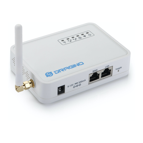
1.6 Hardware Variants The LG01N and OLG01N use the same firmware and have the same feature in the software side. In this document, we will use LG01N as the model number to explain the feature. Model Photo Description LG01N... -
Page 11: Access Lg01N
2. Access LG01N Access and configure LG01 The LG01N is configured as a WiFi AP by factory default. User can access and configure the LG01N after connect to its WiFi network. At the first boot of LG01N, it will auto generate an unsecure WiFi network call dragino-xxxxxx User can use the laptop to connect to this WiFi network. -
Page 12: Typical Network Setup
3.2 Use WAN port to access Internet By default, the LG01N set to use WAN port as network connection. When connect LG01N’s WAN port to router, LG01N will get IP from router and have internet access. The network status is as below:... -
Page 13: Access Internet As A Wifi Client
3.3 Access Internet as a WiFi Client. In the WiFi Client Mode, Dragino acts as a WiFi client and gets IP from uplink router via WiFi. The step to set is as below: Step1: In network -> Wireless, select Radio0 interface and scan. - Page 14 (Note:make sure click the Save & Apply after configure) After successful associate, the WiFi network interface can be seen in the same page: LoRa Gateway User Manual ---Update:2018-12-28 14 / 59...
-
Page 15: Use Built-In 4G Modem For Internet Access
3.4 Use built-in 4G modem for internet access For the LG01N with built-in 4G version, user can configure the modem for internet access. Step 1: Add New Interface LoRa Gateway User Manual ---Update:2018-12-28 15 / 59... - Page 16 Step 2: Configure cellular interface Step 3: Check Result Note: In case you don’t know if your device has 4G modem, you can run lsusb command in SSH access to check, as below: LoRa Gateway User Manual ---Update:2018-12-28 16 / 59...
-
Page 17: Check Internet Connection
3.5 Check Internet connection User can use the diagnostics page to check and analyze Internet connection. LoRa Gateway User Manual ---Update:2018-12-28 17 / 59... -
Page 18: Example 1: Configure As A Lorawan Gateway - Limited Lorawan Mode
LoRaWAN Server is similar. 4.1 Create a gateway in TTN Server Step 1: Get a Unique gateway ID. Every LG01N has a unique gateway id. The id can be found at LoRaWAN page: LoRa Gateway User Manual ---Update:2018-12-28 18 / 59... - Page 19 The gateway id is: a840411b6fc44150 Step 2: Sign up an user account in TTN server Step 3: Create a Gateway in TTN LoRa Gateway User Manual ---Update:2018-12-28 19 / 59...
-
Page 20: Configure Lg01N Gateway
4.2 Configure LG01N Gateway 4.2.1 Configure to connect to LoRaWAN server We should configure the LG01N now to let it connect to TTN network. Make sure your LG01N has Internet Connection first. Step1: Configure LG01N to act as raw forwarder mode... - Page 21 Step2: Input server info and gateway id Choose the correct the server address and gateway ID. Check Result After above settings, the LG01N should be able to connect to TTN, below is the result seen from TTN: LoRa Gateway User Manual ---Update:2018-12-28...
-
Page 22: Configure Lg01'S Radio Frequency
LG01N supports LoRaWAN End Node, in LoRaWAN protocol, it requires LoRaWAN node to send data in a hopping frequency. Since LG01N only support one single frequency, it will only be able to receive the packet which is of the same radio parameters in LG01N. - Page 23 In this section, we will use LoRa Shield and a modify LMIC Library to show how to configure LoRaWAN end node and work in single frequency. LoRa Gateway User Manual ---Update:2018-12-28 23 / 59...
-
Page 24: Preparation
4.3.2 Preparation LoRaWAN End device Hardware: Software Library for LoRaWAN End device: Install this library https://github.com/dragino/arduino-lmic to the Arduino Library path. Before compiling the End Device software, User needs to change the Frequency Band to use with LG02. What user need to change is in the file arduino\libraries\arduino-lmic \src\lmic\config.h. -
Page 25: Test With Otaa Lora End Node (Lora Shield + Uno)
4.3.3 Test with OTAA LoRa end node (LoRa Shield + UNO) Step 1: Create an OTAA device in TTN server -- > Application page. LoRa Gateway User Manual ---Update:2018-12-28 25 / 59... - Page 26 Step 2: Input keys into Arduino Sketch. The sketch for the LoRa Shield is in Arduino –IDE --> Examples -->LMIC_Arduino ttn-otaa Choose Arduino UNO to upload the sketch to LoRa Shield and UNO LoRa Gateway User Manual ---Update:2018-12-28 26 / 59...
- Page 27 Step 3: Check Result for OTAA Note: The LG02_DNWFREQ value in Arduno_LMIC/src/lmic/config.h should match downlink frequency from TTN. TTN shows 868.1 here, So LG02_DNWFREQ should be 868100000 LoRa Gateway User Manual ---Update:2018-12-28 27 / 59...
- Page 28 Downlink message Send out from TTN after the next uplink message arrive. In TTN --> Gateway --> Traffic Downlink message arrives gateway In LG01N --> Service --> Logread Downlink message arrives LoRa Shield In Arduino IDE --> Serial Monitor LoRa Gateway User Manual ---Update:2018-12-28...
-
Page 29: Test With Abp Lora End Node (Lora Shield + Uno)
4.3.4 Test with ABP LoRa end node (LoRa Shield + UNO) Step 1: Create an ABP device in TTN server -- > Application page. And change it to ABP mode. LoRa Gateway User Manual ---Update:2018-12-28 29 / 59... - Page 30 Step 2: Input keys into Arduino Sketch. The sketch for the LoRa Shield is in Arduino –IDE --> Examples -->LMIC_Arduino ttn-abp TTN LoRaWAN End Device page Make sure the Network Session Key and App Session Key are in MSB order...
- Page 31 Step 3: Check Result for Uplink Packet Sent From LoRa Shield. In Arduino IDE --> Serial Monitor Packet Arrive Gateway. In page Service-->logread Packet Arrive TTN. In TTN --> Gateway --> Traffic Packet Arrive TTN Device Page. In TTN --> Application --> Device --> Data...
- Page 32 Downlink message Send out from TTN after the next uplink message arrive. In TTN --> Gateway --> Traffic Downlink message arrives gateway In LG01N --> Service --> Logread Downlink message arrives LoRa Shield In Arduino IDE --> Serial Monitor LoRa Gateway User Manual ---Update:2018-12-28...
-
Page 33: Example 2: Control Lora Radio Directly As General Lora Transceiver
Step 1: Disable packet forward With firmware higher than version LG02_LG08--build-v5.1.1545908833-20181227-1908, select “Disabled” in IoT Service page. Step 2: Use lg02_single_rx_tx to receive, for LG01N, the option [-d] is 2 Usage: lg02_single_rx_tx [-d radio_dev] select radio 1 or 2 (default:1) - Page 34 Then set up a LoRa node to send out LoRa packet, we use LoRa Shield + UNO in this example. The library use in Arduino UNO is LoRa-Master. And the source code is LoRaReceiver. Result screen shot: LoRa Gateway User Manual ---Update:2018-12-28...
- Page 35 Step 3: Use lg02_single_rx_tx to transmit Command: root@dragino-1b6fb0:~# lg02_single_rx_tx -t -d 2 -f 915600000 –m “hello from dragino” Use radio 2 to transmit a message at frequency 9156000000 Set up a LoRa node to send out LoRa packet, we use LoRa Shield + UNO in this example.
-
Page 36: Example 3: Mqtt Transfer Mode
API: the write API key for this channel. 6.2 Step by Step Uplink Test In this section, we will try to program LG01N to uplink data to ThingSpeak. The data flow in this example is as below: We will try the step ② first, after it work as expect, we will integrate it with step ① for a complete uplink example. -
Page 37: Simulate Mqtt Publish Via Pc's Mqtt Tool
6.2.1 MQTT Publish via PC’s MQTT tool Simulate This step is not necessary, it just to help user to understand the MQTT protocol and simulate the MQTT connection to ThingSpeak. Make sure the account info is valid and correct. -
Page 38: Try Mqtt Publish With Lg01N Linux Command
First, we need to make sure the LG01N has internet access. We can log in the SSH and ping an Internet address and see if it get through. As below: LG01N has built-in Linux tool mosquitto_pub. - Page 39 After running this command, we can see the data are updated to ThingSpeak, which has same result as what we did at mqtt.fx So we success to use LG01N to uplink data to ThingSpeak, the mosquitto_pub command is executed in the Linux side, finally, we will have to call...
-
Page 40: Test Lg01N Mqtt Routine Service
6.2.3 Test LG01N MQTT routine service. Above process help us to understand how MQTT works in LG01N, now we can move further, try to use the built-in MQTT routine. Step1: Select MQTT Transfer mode Step2: Configure MQTT parameter. LoRa Gateway User Manual ---Update:2018-12-28... - Page 41 Step3: Simulate channel data The MQTT process will keep checking if there is data in the directory: /var/iot/channels. If there is new data, the process will check if this data match the local channel ID. If match, the process will update it to MQTT server.
- Page 42 So the LG01N will send out this command: mosquitto_pub -h mqtt.thingspeak.com -p 1883 -u dragino1 -P 32W6GMEXYTEQ7049 -i dragino_Client -t channels/396640/ publish/ P07KVY59P5QEY6M6 -m "field1=34&field2=89&status=MQTTPUBLISH" The output in logread –f is: And see update: LoRa Gateway User Manual ---Update:2018-12-28...
-
Page 43: Configure Lora End Node
Configure the Radio channel with the match radio settings frequency as the LoRa End Node Now the LG01N will listen on this LoRa channel. If the received data match the pre-define data format, LG01N will store it in /var/iot/channels/ and the MQTT process can handle it for upload. -
Page 44: Example 4: Tcp Ip Client Mode
7. Example 4: TCP IP Client Mode In the TCP IP Client mode, LG01N can accept LoRa packets and send it to the TCP-IP server. The working topology is as below. In this mode, The Uplink LoRa packets should use a customized format. - Page 45 Step3: Configure TCP Server Info Note: Gateway may receive many LoRa packets, it will only transfer the packet with the same ID as specify in the channel. Step4: About uplink data format The LoRa end node should upload the data with below format: Uplink Format: <Channel_ID>data...
-
Page 46: Linux System
8. Linux System The LG01N bases on OpenWrt Linux System. It is open source, and user are free to configure and modify the inside Linux settings. 8.1 SSH Access for Linux console User can access to the Linux console via SSH protocol. Make sure your PC and the LG01 is in the same network, then use a SSH tool (such as putty) to access it. -
Page 47: Edit And Transfer Files
One of the easiest is through WinSCP utility. After access via WinSCP to the device, use can use a FTP alike window to drag / drop files to the LG01N or Edit the files directly in the windows. Screenshot is as below: 8.3 File System The LG01N has a 16MB flash and a 64MB RAM. - Page 48 "rootfs_data" //inside rootfs, all data store here. "config" // a separate partition doesn't include file system "art" // radio data and board ID. Use df command to see available flash & RAM: tmpfs 30096 30000 0% /tmp...
-
Page 49: Package Maintain System
For example, if user wants to add iperf tool, they can install the related packages and configure LG01N to use iperf Below is some examples opkgs command, more please refer... -
Page 50: Upgrade Linux Firmware
9. Upgrade Linux Firmware We keep improving the LG01N Linux side firmware for new features, bug fixes. The latest firmware can be found on LG01N Firmware & release note The file named as dragino-LG02_LG08----xxxxx-squashfs-sysupgrade.bin is the upgrade Image. There are different methods to upgrade, as below: 9.1 Upgrade via Web UI... -
Page 51: Faq
8 channels. The LG01N only support two channels and can only support limited LoRaWAN protocol. Because of this limitation, if user wants to use a standard LoRaWAN device with LG01N, user has to modify this LoRaWAN node to run in single frequency to work with LG01N. -
Page 52: Can I Develop My Own Software For Lg01N
-software-before-build-the-image 10.5 Can I make my own firmware for LG01N? Where can I find the source code of LG01N? Yes, User can make own firmware for LG01N for branding purpose or add customized application. The LG01N source code and compile instruction can be found at: https://github.com/dragino/openwrt_lede-18.06... -
Page 53: How Can I Reset The Device To Factory Default
Reset via Web UI. Click the button in Web UI --> System --> Back up / Flash firmware --> Perform Reset Method 2: Reset in Linux console, command is below: root@dragino-1b8288:~# firstboot This will erase all settings and remove any installed packages. Are you sure? [N/y] LoRa Gateway User Manual ---Update:2018-12-28... -
Page 54: More Faqs About General Lora Questions
/dev/mtdblock4 is mounted as /overlay, only erasing files root@dragino-1b8288:~# reboot 10.8 More FAQs about general LoRa questions We keep updating more FAQs in our WiKi about some general questions. The link is here: http://wiki.dragino.com/index.php?title=LoRa_Questions LoRa Gateway User Manual ---Update:2018-12-28... -
Page 55: Trouble Shooting
11.1 I get kernel error when install new package, how to fix? In some case, when install package, it will generate kernel error such as below: root@dragino-16c538:~# opkg install kmod-dragino2-si3217x_3.10.49+0.2-1_ar71xx.ipk Installing kmod-dragino2-si3217x (3.10.49+0.2-1) to root... Collected errors: * satisfy_dependencies_for: Cannot satisfy the following dependencies for kmod-dragino2-si3217x: kernel (= 3.10.49-1-4917516478a753314254643facdf360a) *... -
Page 56: How To Recover The Lg01N If Firmware Crash
11.2 How to recover the LG01N if firmware crash LG01N provides user a full control on its Linux system, it is possible that the device will brick and can’t boot after improper modification in some booting files. In this case, user can recover the whole Linux system by uploading a new firmware via Web Failsafe mode. -
Page 57: I Configured Lg01N For Wifi Access And Lost Its Ip. What To Do Now
The LG01 has a fall-back ip in its LAN port. This IP is always enabled so user can use fall back ip to access LG01N no matter what the WiFi IP is. The fall back ip is useful for connect and debug the unit. -
Page 58: Order Info
13. Packing Info Package Includes: LG01N or OLG01N LoRa Gateway x 1 Stick Antenna for LoRa RF part. Frequency is one of 433 or 868 or 915Mhz depends the model ordered Power Adapter: EU/AU/US type power adapter depends on country to be used ... - Page 59 Source code for LG01N LoRa Gateway https://github.com/dragino/openwrt_lede-18.06 OpenWrt official Wiki http://www.openwrt.org/ Download of this manual or Update version http://www.dragino.com/downloads/index.php?dir=UserManual/LG02_OLG02/ LMIC library for Arduino LoRaWAN end device use with LG01N. https://github.com/dragino/arduino-lmic LoRa Gateway User Manual ---Update:2018-12-28 59 / 59...
Need help?
Do you have a question about the LG01N and is the answer not in the manual?
Questions and answers