Table of Contents
Advertisement
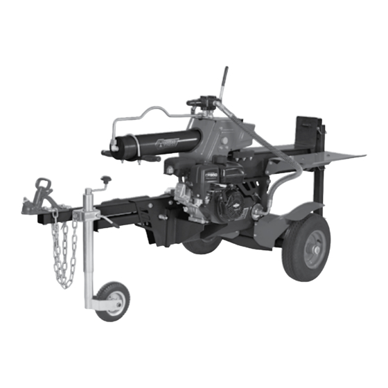
PETROL
LOG SPLITTER
• 22 TONNE SPLITTING FORCE
• 6.5HP BRIGGS & STRATTON ENGINE
• HORIZONTAL AND VERTICAL
INSTRUCTION MANUAL
WARNING: Read all safety warnings and instructions before use. Failure
to follow the warnings and instructions may result in electric shock, fire and/or
serious injury. Save these instructions for future reference.
1217
Advertisement
Table of Contents

Related Manuals for Full Boar FBLS-22T

Summary of Contents for Full Boar FBLS-22T
-
Page 1: Log Splitter
KNOW YOUR PRODUCT PETROL LOG SPLITTER • 22 TONNE SPLITTING FORCE • 6.5HP BRIGGS & STRATTON ENGINE • HORIZONTAL AND VERTICAL OPERATION INSTRUCTION MANUAL WARNING: Read all safety warnings and instructions before use. Failure to follow the warnings and instructions may result in electric shock, fire and/or serious injury. -
Page 2: Specifications
SPECIFICATIONS - MODEL NO. FBLS-22T Engine specifications: Log splitter specifications: Power: 6.5HP Splitting force: 22 Tonne Type: 4 Stroke, air cooled Log length maximum: 600mm Fuel type: 91 Oct unleaded Table size: 610 x 310mm Fuel tank capacity: 3.0 litres... -
Page 3: Assembly
KNOW YOUR PRODUCT (cont.) Pivot pin Ø18 x 135 x 1 R-Clip M10 x 35 x 6 M12 x 80 x 2 Axle Nut & Washer Split Pin 4 x 50 Wheel Cap M12 x 30 x 4 Axle Nut & Washer Split Pin 4 x 50 Wheel Cap M10 x 25 x 2... -
Page 4: Table Of Contents
TABLE OF CONTENTS SPECIFICATIONS............Page 02 KNOW YOUR PRODUCT........... Page 02 INTRODUCTION............Page 05 SAFETY INSTRUCTIONS........... Page 05 ASSEMBLY..............Page 11 FEATURES AND CONTROLS........Page 24 SETUP AND PREPARATION........Page 27 OPERATION............... Page 31 TRANSPORTING............Page 34 MAINTENANCE............Page 36 STORAGE.............. -
Page 5: Introduction
INTRODUCTION Congratulations on purchasing a Full Boar petrol log splitter. It has been designed to split wood logs for use as firewood for a wood heater or fireplace. The log splitter will only split logs lengthwise with the grain and is capable of splitting most Australian hardwoods. -
Page 6: Operation
GENERAL SAFETY WARNINGS SAVE THESE INSTRUCTIONS Understanding your log splitter Read this manual and labels affixed to the machine to understand its limitations and potential hazards. Be thoroughly familiar with the controls and their proper operation. Know how to stop the machine and disengage the controls quickly. -
Page 7: Transporting
GENERAL SAFETY WARNINGS (cont.) Inspect your log splitter Check your machine before starting it. Keep guards in place and in working order. Make sure all nuts, bolts, etc., are securely tightened. Never operate the machine when it is in need of repair or is in poor mechanical condition. Replace damaged, missing, or failed parts before using it. - Page 8 GENERAL SAFETY WARNINGS (cont.) Store fuel in containers specifically designed and approved for this purpose. Store fuel in a cool, well-ventilated area, safely away from sparks, open flames, or other sources of ignition. Never store fuel or a machine with fuel in the tank inside a building where fumes may reach a spark, open flame, or any other source of ignition, such as a water heater, furnace, or clothes dryer.
- Page 9 PETROL LOG SPLITTER SAFETY WARNINGS IMPORTANT! When using the equipment, a few safety precautions must be observed to avoid injuries and damage. Please read the complete operating manual with due care. Keep this manual in a safe place so that the information is available at all times.
- Page 10 PETROL LOG SPLITTER SAFETY WARNINGS (cont.) KNOW YOUR PRODUCT Log splitter use and care Never operate the machine without good visibility or light. Never attempt to split wood across the grain. The log splitter was not designed for cross grain splitting. Always block the front and back of both wheels to prevent unintended movement.
- Page 11 ASSEMBLY It is required that a minimum of two people assemble the log splitter. CAUTION! Some parts are over 16kg, two-person lift is required to avoid injury. Joining the beam and motor assembly Tools required (not supplied): ¥ Ring/open end spanner 16mm x 2, Soft face hammer Pivot pin 1.
- Page 12 ASSEMBLY (cont.) 4. With the hole in the beam pivot bracket aligned with the pivot hole on the pivot mount, insert the pivot pin using a soft face hammer and secure with the washer and R-clip (fig. 3). 5. Disassemble the support leg (7) from the R-Clip log splitter by removing the 3 bolts and Pivot Pin...
- Page 13 Roll Pin 6 x 40 M8 x 20 ASSEMBLY (cont.) M12 x 35 x 8 Wedge cover guard Tools required (not supplied): M10 x 25 ¥ 16mm Socket with ratchet. 1. Use assembly hardware M10 x 35 x 6 M8 x 20 2.
- Page 14 M12 x 30 x 4 ASSEMBLY (cont.) Axle Nut & Washer Split Pin 4 x 50 Drawbar assembly Wheel Cap Tools required (not supplied): ¥ 18mm Ring/open end spanner x 2. 1. Use assembly hardware M12 x 80 x 2 2.
- Page 15 ASSEMBLY (cont.) Bearing Sleeve 3. Remove the anti-dust sleeves from a wheel Bearing (11) while keeping the bearings and anti- Sleeve dust washer in place (fig. 10). Anti-dust Washer Anti-dust Washer Fig. 10 4. Slide a wheel (11) with valve stem facing Bearing out onto the axle (24) on one side, then Split Pin...
- Page 16 M8 x 45 ASSEMBLY (cont.) 2. Use Remove two M8 x 45 bolts, washer, and nuts (fig. 12). M8 x 45 Fig. 12 3. Hold the beam (16) and carefully move the log splitter until the upper bracket of the Beam Assembly M8 x 45 wheel axle is against the wooden block...
- Page 17 ASSEMBLY (cont.) 5. Move the Lock pin and R-clip from the upper hole and insert the lock pin into the lower hole. Ensure the beam (16) is locked in the vertical position (fig. 15). Upper Hole Lower Hole Fig. 15 6.
- Page 18 M12 x 80 x 2 ASSEMBLY (cont.) U-shaped Lock Pin 3. Follow the same procedure on page 15, step 3 - 8, to assemble the second wheel (11) (fig. 17). Washer & Sping Nut & Washer Bearing Roll Pin 6 x 40 Upper Bracket Split Pin Axle Nut...
- Page 19 ASSEMBLY (cont.) Jockey wheel assembly 1. Place the jockey wheel (6) into its bracket on the drawbar (19) (fig. 19). 2. Secure by tightening the locking pin on the bracket (fig. 20). Pivot pin Ø18 x 135 x 1 R-Clip M12 x 30 x 4 Axle Nut &...
- Page 20 ASSEMBLY (cont.) 4. Fully insert the U-shaped lock pin allowing the short end to pass through the lower hole (fig. 22). Lower Hole Fig. 22 5. To secure the U-shaped lock pin, insert the Roll Pin roll pin through the support leg (7) locating hole and into the U-shaped lock pin hole.
- Page 21 Mounting Hole M12 x 80 x 2 M12 x 30 x 4 ASSEMBLY (cont.) Log Cradle (engine side) U-shaped Lock Pin Axle Nut & Washer Wheel guards assembly Split Pin 4 x 50 Washer & Sping Tools required (not supplied): Wheel Cap Roll Pin 6 x 40...
- Page 22 Pivot pin Ø18 x 135 x 1 R-Clip ASSEMBLY (cont.) M12 x 30 x 4 Muffler assembly Axle Nut & Washer Tools required (not supplied): ¥ 13mm Ring/open end spanner Split Pin 4 x 50 Wheel Cap 1. Remove the plastic cover by removing the nuts and washers (fig.
- Page 23 Washer & Sping 6 x 40 Roll Pin ASSEMBLY (cont.) M8 x 20 Log table assembly Tools required (not supplied): M12 x 35 x 8 ¥ 16mm Ring/open end spanner. M10 x 25 1. Use assembly hardware M10 x 35 x 6 Dome Head Fig.
- Page 24 Log Cradle (engine side) Flat Washer Spring Washer FEATURES AND CONTROLS Log cradle The log cradles are designed to catch the log after it is split (fig. 31). 2 position function: − The inside hole position is to centre the logs on the beam. −...
- Page 25 FEATURES AND CONTROLS (cont.) Tow hitch Located at the end of the drawbar and attaches to a 2 inch tow ball for transporting your log splitter by vehicle. See the Transporting section for instruction (fig. 36). Fig. 36 Control lever Neutral Position Reverse Position The control lever is used to move the wedge up and down to...
- Page 26 FEATURES AND CONTROLS (cont.) Engine on/off switch The engine switch has two positions (fig. 41), OFF: engine will not start or run. ON: engine will start and run. Throttle lever Fig. 41 Is used to regulate the rotation speed of the engine (fig. 42 ). Throttle ¥...
- Page 27 SETUP & PREPARATION Horizontal position to vertical position 1. Remove the rear leg (13) from its current position (fig. 45). 2. Release the horizontal lock latch Fig. 45 3. Hold the hydraulic cylinder handle (3) and slowly stand the assembled beam on the end plate in the vertical position (fig.
- Page 28 SETUP & PREPARATION (cont.) Vertical position to horizontal position 1. Remove the R-clip and lock pin from the lower hole (fig. 48). Fig. 48 2. Hold the hydraulic cylinder handle (3) and slowly lower the beam (fig. 49). CAUTION! Do not let the beam suddenly drop.
- Page 29 SETUP & PREPARATION (cont.) 4. Refit rear support leg (13) in the lowermost position, hold in place with both pins to lock in position (fig. 51). LOCK Fig. 51...
- Page 30 SETUP & PREPARATION (cont.) WARNING! Be sure to stop the engine before refuelling. Allow the engine to cool before adding fuel. Do not smoke while refuelling. Adding fuel Only use unleaded 91 RON (Research Octane Number) petrol. Purchase fuel in quantities that can be used every 30 days to prevent gum or foaming inside the container and/or fuel tank (fig.
-
Page 31: Starting The Engine
OPERATION Starting the engine Before starting work, hydraulic pipes and hoses shall be inspected and the stopping devices shall be tested. The log splitter must be set up on level surface, free from obstructions. 1. Ensure the control lever is in the neutral position. 2. -
Page 32: Stopping The Engine
OPERATION (cont.) Stopping the engine 1. Ensure the wedge is in the retracted position and the control lever is in the neutral position. 2. Move the throttle lever fully right towards the ..indicator (fig. 61), move the engine on/off switch to the OFF position (fig. 62) and fuel lever left, closed position (fig.63). Fig. - Page 33 OPERATION (cont.) ¥ The splitting operation of the machine is designed to be activated by one person only. WARNING! Stand in safe working zone, so feet are not in the path of falling logs. HORIZONTAL OPERATING ZONE VERTICAL OPERATING ZONE WARNING! Do not hold wood in position to be split, with any part of your body once the control lever is moved into the forward or reverse position.
- Page 34 TRANSPORTING Moving the log splitter by hand WARNING! The log splitter is heavy. It can crush and cause serious injury if it rolls out of control or tips over. 1. Ensure the log splitter is in the horizontal position with the lock latch engaged. 2.
- Page 35 TRANSPORTING (cont.) Towing WARNING! Not for towing on public roads. 1. Ensure the log splitter is in the horizontal position with the lock latch engaged. 2. The engine is off and the fuel lever is fully left, closed position. 3. Check the tires to ensure they are at the recommended tyre pressure (30 PSI). 4.
- Page 36 MAINTENANCE ¥ Inspect and maintain the log splitter before each use. If the log splitter has been used previously, it must be inspected and maintained before each subsequent use. ¥ Always shut off the engine and relieve system pressure before inspecting, cleaning, adjusting, or repairing the splitter.
- Page 37 MAINTENANCE (cont.) 8. Ensure dipstick is securely tighten after oil has been topped up. 9. Start the engine and use the control lever to extend and retract the wedge five times to remove air from the high pressure lines. 10. With the wedge retracted and engine off, check the oil level again. Fill if necessary. 11.
- Page 38 STORAGE Follow the instructions below for storing your log splitter between uses. 1. Retract the wedge completely to keep the rod protected from corrosion. 2. Allow the log splitter to cool before storing. 3. Clear the debris from the beam, wedge, and end plate. Use a damp cloth to clear exterior surfaces of the engine and log splitter.
- Page 39 TROUBLESHOOTING Symptom Possible Cause Suggested Solution Wedge movement is Air in the hydraulic oil Purge air by extending and retract- slow or erratic system ing the wedge several times until motion is smooth Debris lodged in beam Clear debris from beam guides Low hydraulic oil Check oil level and add as needed.
- Page 40 DESCRIPTION OF SYMBOLS Warning Regulator compliance mark Read these instructions carefully. Wear safety footwear Wear eye protection. Wear protective gloves Wear hearing protection. Operate the log splitter on Be aware of thrown objects level surfaces. Stay o slopes and slippery surfaces. Do not touch parts that are Do not remove or tamper with the hot from operation.
- Page 41 CONTENTS 1 x FBLS-22T Petrol log splitter 1 x Support leg- front 1 x Wheel guard -engine side 1 x Wheel guard - right side 1 x Log cradle - engine side 1 x Log cradle - right side 1 x Hydraulic cylinder handle...
-
Page 44: Warranty
WARRANTY YOUR WARRANTY FORM SHOULD BE RETAINED BY YOU AT ALL TIMES. IN ORDER TO MAKE A CLAIM UNDER THIS WARRANTY YOU MUST RETURN THE PRODUCT TO YOUR NEAREST BUNNINGS WAREHOUSE (see www.bunnings.com.au or www.bunnings.co.nz for store locations) WITH YOUR BUNNINGS REGISTER RECEIPT. PRIOR TO RETURNING YOUR PRODUCT FOR WARRANTY PLEASE TELEPHONE OUR CUSTOMER SERVICE HELPLINE: Australia 1800 069 486 New Zealand 0508 069 486...
Need help?
Do you have a question about the FBLS-22T and is the answer not in the manual?
Questions and answers