Table of Contents
Advertisement
Quick Links
1S24 User Guide
Arc Fault Monitoring System
relay monitoring systems pty ltd
Advanced Protection Devices
User Guide
www.rmspl.com.au
Visit
for the latest product information.
Due to RMS continuous product improvement policy this information is subject to change without notice. 1S24_Guide/Iss G/07/01/2019
Advertisement
Table of Contents
Troubleshooting

Summary of Contents for RMS Mors Smitt 1S24
- Page 1 1S24 User Guide Arc Fault Monitoring System relay monitoring systems pty ltd Advanced Protection Devices User Guide www.rmspl.com.au Visit for the latest product information. Due to RMS continuous product improvement policy this information is subject to change without notice. 1S24_Guide/Iss G/07/01/2019...
- Page 2 User Guide About This Manual This User Guide covers all 1S24 relays manufactured from August 2017. Earlier relays do not necessarily incorporate all the features described. Our policy of continuous development means that extra features & functionality may have been added.
- Page 3 Part How this Guide is Organised This guide is divided into three parts: Part 1 Overview Part 2 Documentation Part 3 Application www.rmspl.com.au Visit for the latest product information.Page Due to RMS continuous product improvement policy this information is subject to change without notice. 1S24_Guide/Iss G/07/01/2019...
- Page 4 Product Test Manual Each 1S24 version has a specific PTM which provides details on the unique attributes of the relay. Each PTM includes the following information: • Specific technical variations from the standard model if applicable •...
-
Page 5: Table Of Contents
Communications ......................27 Physical Connections .......................... 27 IEC61850 Communication Topologies ....................28 IP Addressing ............................29 1S24 Arc Fault Monitor Configuration ................ 30 Web Browser Session ......................... 30 Relay Build ............................32 IP Configuration ........................... 32 Arc Configuration ..........................33 State ................................ - Page 6 1S24 IEC61850 Configuration ..................59 The .cid File ............................59 FTP 1S24.cid File ..........................59 Rebooting the 1S24 with the New 1S24.cid File ................. 61 Subscribing Reyrolle 7SR22 IED Configuration ............65 Logic Configuration ..........................65 User Output Allocation ........................65 Current Check Logic ..........................
- Page 7 General Ethernet Communications Trouble Shooting ................83 IEC61850 GOOSE Message Trouble Shooting ..................84 Interpreting Vx Auxiliary Supply or Relay Healthy Indications ..............84 Using IED SCOUT IEC61850 GOOSE Message Trouble Shooting ............86 Page 3 www.rmspl.com.au Visit for the latest product information Page Due to RMS continuous product improvement policy this information is subject to change without notice.
-
Page 8: Sensor Installation
Sensor Installation 1S30 Sensors The 1S30 sensor is available as a single detector or dual detector package. The 1S30A single detector version is depicted below showing the location of the detection window and the approximate coverage zone: Detection window Coverage Zone The recommended spacing for the 1S30A single detectors is approximately 5 - 6 m to ensure adequate detection overlap. - Page 9 The 1S30B Dual detector version provides an additional detection window for dual zones of coverage as depicted below : Detection windows The recommended spacing for the 1S30B single detectors is approximately 5 - 6 m to ensure adequate detection overlap, this combination provides an overall coverage zone of approximately 10 - 12 m.
-
Page 10: Sensor Placement
The 1S30A and 1S30B sensors may also be mixed to provide various coverage combinations, again spacing’s of approximately 5 - 6 m should be observed to ensure adequate detection overlap. 10 - 12m Sensor Placement Sensors need to be mounted to provide full coverage of the switchgear cubicles to be protected. Where the protected zone is larger than the sensor coverage then the use of multiple sensors is required. -
Page 11: Example Sensor Placement
Example Sensor Placement The following are some typical examples of sensor placement. Sensor placement inside CB racking chamber Sensor placement inside busbar chamber Page 7 www.rmspl.com.au Visit for the latest product information Page Due to RMS continuous product improvement policy this information is subject to change without notice. 1S24_Guide/Iss G/07/01/2019... - Page 12 Sensor placement inside cable termination chamber Sensor placement for switchgear Busbar coverage (External through Hole Detector) Page 8 www.rmspl.com.au Visit for the latest product information Page Due to RMS continuous product improvement policy this information is subject to change without notice. 1S24_Guide/Iss G/07/01/2019...
- Page 13 Sensor placement near Low Voltage Contactor for a Variable Speed Drive Sensor placement for Switchgear cable termination chamber (External through Hole Detector) Page 9 www.rmspl.com.au Visit for the latest product information Page Due to RMS continuous product improvement policy this information is subject to change without notice. 1S24_Guide/Iss G/07/01/2019...
- Page 14 Sensor placement for end of Bus chamber (External through Hole Detector) Sensor placement for Switchgear cable termination chamber (External through Hole Detector) Page 10 www.rmspl.com.au Visit for the latest product information Page Due to RMS continuous product improvement policy this information is subject to change without notice. 1S24_Guide/Iss G/07/01/2019...
-
Page 15: 1S40 Linear Sensors
1S40 Linear Sensors The 1S40 linear sensor may be applied to protect large volumes where multiple point sensors would otherwise be required. A separate 1S40 linear sensor is required for each segregated protection zone. The linear sensor kits provide both a black link fibre and a translucent arc sensor fibre. The translucent fibre is located within the detection zone and black link fibres allow routing of the linear sensor back to the relay. - Page 16 The 1S40 kit comprises of lengths of black link fibre (pre-terminated with a duplex connector for relay connection), unterminated translucent fibre, 2 x optical fibre couplers and a fibre optic fibre cutter. Black Link Fibre Assembly Translucent Sensor Fibre Optic Fibre Couplers Optic Fibre Cutter The individual components are combined per the diagram below : Page 12...
-
Page 17: 1S40 Linear Sensor Assembly
2. Receive Section (section of bare and clad fibre back to the relay Rx connection) must be 3. Arc Sensor Section (section of bare fibre) must be 30m The chosen Transmission Section Length must also be configured in the 1S24 Fibre Loop Sensor configuration screen – refer to Linear Sensor Configuration. -
Page 18: 1S40 Linear Sensor Compartment Fixing
1S40 Linear Sensor Compartment Fixing The optic fibre couplers may be positioned and held in place with the provided fixing nuts at a compartment interface. The optic fibres may be retained using cable ties or silicon adhesive. When using silicon adhesive no more than 10% of the sensor fibre shall be masked by the silicon. -
Page 19: Scheme Wiring
Scheme Wiring 1S24 Connection diagrams 2 Trip Output Version Page 15 www.rmspl.com.au Visit for the latest product information Page Due to RMS continuous product improvement policy this information is subject to change without notice. 1S24_Guide/Iss G/07/01/2019... - Page 20 3 Trip Output Version The above diagrams show the 1S24 connections. The connected sensor inputs need to be enabled and unused inputs disabled via the Web browser configuration tool. This is essential to: • Allow connected sensor inputs to operate for an ARC Fault •...
-
Page 21: Linear Sensor Connections
Linear Sensor Connections A unit with 1S24 Linear sensor connections is pictured below showing the connection points for the Linear sensors: Linear Sensor equipped units provide inputs for 2 Linear sensors and 12 point sensors. Each Linear Sensor input provides a Transmit (TX) and Receive (RX) set of connections. -
Page 22: Example Schematic - Direct Arc Trip Only Application
Example Schematic – Direct Arc Trip Only Application + POS 4 (+) 10 (+) 13 (+) 16 (+) 1S24 3 (-) 11 (-) 14 (-) 17(-) CIRCUIT BREAKER TRIP COIL + NEG CIRCUIT BREAKER SHOWN IN THE OPEN POSITION AND RELAY SHOWN... -
Page 23: Example Schematic - Current Checked Arc Trip Application
Example Schematic – Current Checked Arc Trip Application + POS Current Check Relay >> 4 (+) 10 (+) 13 (+) 16 (+) 1S24 3 (-) 11 (-) 14 (-) 17(-) CIRCUIT BREAKER TRIP COIL + NEG CIRCUIT BREAKER SHOWN IN THE... -
Page 24: Terminal Layout And Module Dimensions
Terminal Layout and Module Dimensions Surface or Din Rail Mounting Page 20 www.rmspl.com.au Visit for the latest product information Page Due to RMS continuous product improvement policy this information is subject to change without notice. 1S24_Guide/Iss G/07/01/2019... - Page 25 The drilling plan for surface mounting is shown below: The module may alternatively be mounted on a din rail by using 2 optional din rail mounting kits (2 x RMS P/N: 290407157). Page 21 www.rmspl.com.au Visit for the latest product information Page Due to RMS continuous product improvement policy this information is subject to change without notice.
- Page 26 The recommended keep out zones to allow for cable terminations are shown below: Page 22 www.rmspl.com.au Visit for the latest product information Page Due to RMS continuous product improvement policy this information is subject to change without notice. 1S24_Guide/Iss G/07/01/2019...
-
Page 27: Horizontal Or Vertical Flush Mounting
Horizontal or Vertical Flush Mounting The Horizontal or Vertical module options allow for rack frame or flush panel mounting. Page 23 www.rmspl.com.au Visit for the latest product information Page Due to RMS continuous product improvement policy this information is subject to change without notice. 1S24_Guide/Iss G/07/01/2019... - Page 28 Rear view of Terminals: The cutout dimensions for flush mounting are shown below: The recommended keepout zones to allow for cable terminations are shown below: Page 24 www.rmspl.com.au Visit for the latest product information Page Due to RMS continuous product improvement policy this information is subject to change without notice. 1S24_Guide/Iss G/07/01/2019...
- Page 29 Page 25 www.rmspl.com.au Visit for the latest product information Page Due to RMS continuous product improvement policy this information is subject to change without notice. 1S24_Guide/Iss G/07/01/2019...
-
Page 30: Custom Labels
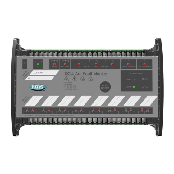
Custom Labels The 1S24 front panel makes provision for two (2) custom labels, one label identifies the sensor location and the remaining label provides IED identification and IP address details. The default labels supplied with the relay may be marked up by hand or alternatively custom labels may be produced using the template provided on the RMS website, printed and slipped behind the clear windows on the front panel as depicted below. -
Page 31: Communications
Communications Physical Connections The 1S24 is ordered with either of the following Ethernet connection options: Standard Single Port : RJ45 10Base-T / 100Base-TX In the single port option the RJ45 port is utilised for connection to an IEC61850 station bus LAN for Goose messaging purposes and for device configuration. -
Page 32: Iec61850 Communication Topologies
The 1S24 IED employs IEC61850 Goose messaging to convey the operation of ARC Fault Sensors and may be used with one or many subscribing IEDs to deploy ARC Fault protection schemes. A 1S24 or many 1S24 Arc Fault Monitors may be connected to a Station Bus Lan as shown below: 1S24... -
Page 33: Ip Addressing
Reconfiguration of the 1S24 IP address may be required according to the IP addressing defined in the IEC61850 substation configuration, any subsequent web browser sessions will need to utilise the reconfigured IP address. -
Page 34: 1S24 Arc Fault Monitor Configuration
Direct connection to a PC or connection via a LAN is possible using a standard Ethernet patch lead. Whether the communication is direct or via a LAN, both the PC and the 1S24 need to have IP addressing within the same network. - Page 35 The factory default username and password is: Username: admin Password: RMS The username and password need only be entered once for each web server session and allows for multiple setting changes with access automatically timing out after 2 minutes of inactivity. Page 31 www.rmspl.com.au Visit...
-
Page 36: Relay Build
Relay Build The Relay Build screen provides device details such as the of the Serial Number and Firmware version. The Password may be changed at this point by entering your new password and pressing the Change button, enter the user name and previous password if prompted. IP Configuration The IP Configuration screen displays and allows editing of the IP address parameters for the RJ45 port, Fibre port, Gateway and the SNTP Server. -
Page 37: Arc Configuration
For time stamping in accordance to the IEC61850 standard an SNTP server is required. The SNTP server IP address can be set in the IP Configuration screen but if left blank the 1S24 will attempt to find a default SNTP server if available. -
Page 38: State
Each sensor input has 4 settable parameters: State Armed or disabled, defines if the Sensor input is enabled or disabled, click on the field to change the state and enter the user name and password if prompted. Trip 1 Yes or No, determines if the Sensor input operates the Trip 1 output, click on the field to change the state and enter the user name and password if prompted. -
Page 39: Linear Sensor Configuration
Linear Sensor Configuration 1S24 relays fitted with Linear Sensor inputs provide 12 point sensor inputs and 2 Linear Sensor inputs denoted 13 and 14. For Linear Sensor inputs that have a Linear Sensor connected there is a need to configure the Fibre Cable Topology to ensure correct arc detection and supervision. -
Page 40: Arc Status
Arc Status The Arc Status screen provides status information on up to 16 sensors inputs. State The State column determines the state of each sensor input. The following states are reported: Disabled ARC Sensor is disabled Armed ARC Sensor is armed Tripped ARC detected (changes for the period of the trip) Failed... -
Page 41: Count
Summary of 1S24 SARC Configuration The following steps outline the 1S24 SARC Configuration: ✓ Establish a Web Browser session using the default IP address ✓ Set up the IP addressing for the SNTP server ✓... -
Page 42: Example Iec61850 Substation Configuration
The following example will demonstrate the process of implementing an ARC Fault Protection scheme using IEC61850 Goose messaging in conjunction with other IEC61850 equipped IEDs. The example will comprise of a 1S24 Arc Fault Monitor used in conjunction with subscribing Reyrolle 7SR22 Argus relays with IEC61850 communications and implemented with the Reydisp Manager productivity tool embedded with the optional Digsi System configurator. -
Page 43: Arc Fault Scheme
Arc Fault Scheme The single line schematic arrangement of the application example is shown in the diagram below: TR1 LT CB Feeder 1A CB Arc Fault coverage is to be provided to the bus, circuit breaker chambers and cable termination chambers and shall be current checked with an overcurrent relay. - Page 44 Sensor connections to 1S24 1S24 The scheme comprises of 1S30 sensors connected to a 1S24 Arc Fault Monitor, providing ARC Fault coverage of the coloured protection zones. The 1S24 provides the SARC Logical Node for the operation of Arc Fault Sensors.
-
Page 45: 1S24 Sarc Allocation
1S24 SARC Allocation In the proposed scheme we have 6 Arc Fault Sensors installed providing coverage for 5 distinct protection zones. The individual SARCs are allocated as follows: Zone Coverage Colour Number of Sensors SARC Allocation Feeder Exit SARC 1... -
Page 46: 1S24 Source Arc Fault Detector Points
1S24 Arc Fault Detector 6 7SR22 Single Point Input GGIO Allocation The 7SR22 relay will subscribe to SARC Goose messages broadcast by the 1S24 IED and shall assign subscribed SARCs to Single Point Input GGIO as follows: Destination 7SR22 Relay Goose Single Point Inputs... - Page 47 A screenshot of Reydisp Manager is shown below: To create a new project choose File and New. Page 43 www.rmspl.com.au Visit for the latest product information Page Due to RMS continuous product improvement policy this information is subject to change without notice. 1S24_Guide/Iss G/07/01/2019...
- Page 48 Fill in the details including where you want the project file to be stored and hit OK. The new project has been created. Page 44 www.rmspl.com.au Visit for the latest product information Page Due to RMS continuous product improvement policy this information is subject to change without notice. 1S24_Guide/Iss G/07/01/2019...
-
Page 49: Populating Ieds In The Iec 61850 Project
Populating IEDs In the IEC 61850 Project We now need to populate the project with our IEDs, firstly the Reyrolle 7SR22. Choose Insert and Device and you will be presented with the following screen. Select the required relay, for this example we will choose a 7SR2202-2AA77-0CA0 ensure that the MLFB code is correctly filled. - Page 50 The 7SR22 IED has been added to your project. Continue adding Reyrolle IEDs as required using the same process. Nominate a meaningful IED name for each IED by right clicking on the IED and choosing properties. Page 46 www.rmspl.com.au Visit for the latest product information Page Due to RMS continuous product improvement policy this information is subject to change without notice.
- Page 51 Choose the IEC 61850 tab and enter a name in the IED Name field. Next we will add the RMS 1S24 IED which is added as a Third Party ICD File. You will need to have the 1S24 ICD file which is available through RMS.
- Page 52 The 1S24 IED has now been added to your project. You can nominate a meaningful IED name for the 1S24 IED by right clicking on the IED and choosing properties. Now we will add an IEC61850 Station, choose Insert and Station.
- Page 53 We can give the Station a meaningful name by editing the Item Name. We then nominate the Station Devices to be included in the Station by right clicking on the Station and choosing properties. Select Station Devices and you will see a selection of available unassigned IEDs Page 49 www.rmspl.com.au Visit...
- Page 54 Select the IEDs Press Add to Station. Press OK to Assign the Devices to the Station. Page 50 www.rmspl.com.au Visit for the latest product information Page Due to RMS continuous product improvement policy this information is subject to change without notice. 1S24_Guide/Iss G/07/01/2019...
-
Page 55: System Configuration - Network View
System Configuration – Network View We now need to configure the IP Addressing for our Station LAN and the Goose Linkages for our Goose messages. With the Station highlighted Double Click the System Configurator Button, this will start the Digsi System Configurator in the Network view. - Page 56 Clicking on the Subnet will reveal the IP Start address, Subnet mask and standard gateway settings. We can set the IP start address for our network for convenience, in this case 192.168.0.1. The Standard Gateway may also be set at this point if one exists. Page 52 www.rmspl.com.au Visit...
- Page 57 Expanding Subnet1 will reveal the IEDs that we previously assigned to the Station. The individual devices may be selected to set their IP addresses. Alternatively at the Subnet level the IP addressing may be automatically allocated starting at the IP start address previously set for the Subnet by pressing the auto IP button. Page 53 www.rmspl.com.au Visit...
-
Page 58: System Configuration - Link View
We’ll choose to auto allocate the IP addressing, the result is shown below with the IP address of each device being incremented and unique. System Configuration – Link View With the network addressing having been completed we’ll now create our GOOSE applications and associated GOOSE linkages. - Page 59 The Applications window lists all the applications by Station, drilling down into the RMS station will reveal the Subnets and any associated reports or GOOSE applications. An existing GOOSE application may be used or alternatively a New GOOSE application created. For our example we’ll use the existing GOOSE application 1, selecting this application reveals the associated IEDs as sources and destinations.
- Page 60 Firstly we’ll select the RMS_1S24 IED and expand RMS_SARC1 and choose FADet to Add as a Source. Once Added as a source it will appear in the interconnections. In turn add all of the required source SARCs. Page 56 www.rmspl.com.au Visit for the latest product information Page Due to RMS continuous product improvement policy this information is subject to change without notice.
- Page 61 The SARCs are linked to the respective 7SR22 IED Single Point Input GGIO chosen from the Destinations window (refer also to the Allocation table in the earlier part of this example). With the linkages complete save the configuration. Page 57 www.rmspl.com.au Visit for the latest product information Page...
-
Page 62: Creating The 1S24 .Cid File
We know need to create a .cid file which we will use at a later stage of the IED Configuration process. Go to the Network screen, select the 1S24 IED, right click and select Export IEC61850 device configuration. Save the file for later 1S24 configuration. -
Page 63: 1S24 Iec61850 Configuration
1S24 and to FTP the .cid file. Download @CHIPTOOL for free from: http://www.beck-ipc.com/en/download/licence.asp?id=chiptool_install&l=1 Run @CHIPTOOL on the PC. The Tool will detect any 1S24 devices on the network as seen by the screen shot below: Page 59 www.rmspl.com.au Visit for the latest product information Page... - Page 64 You will be presented with 2 file directories; the left side is the source directory and the right side A:/ is the 1S24. Locate and select the saved 1S24.cid file created earlier, right click on the file and copy it to the A:/ drive.
-
Page 65: Rebooting The 1S24 With The New 1S24.Cid File
Once copied, ensure that any existing 1S24.cid file in the A:/ drive is renamed or deleted (right click on the file for renaming deletion options). Then select the copied file in the A:/ drive, right click and ensure it is renamed as 1S24.cid. Rebooting the 1S24 with the New 1S24.cid File A reboot of the 1S24 is required once the new 1S24.cid file has been loaded. - Page 66 User : tel Password : tel Use CTRL-F to check the context. You need to be in Shell. CTRL-F to switch the context to Shell. Page 62 www.rmspl.com.au Visit for the latest product information Page Due to RMS continuous product improvement policy this information is subject to change without notice. 1S24_Guide/Iss G/07/01/2019...
- Page 67 Press enter to make the command prompt visible. Page 63 www.rmspl.com.au Visit for the latest product information Page Due to RMS continuous product improvement policy this information is subject to change without notice. 1S24_Guide/Iss G/07/01/2019...
- Page 68 Type in Reboot at the command prompt, the 1S24 will now restart and the LEDs indicate per a normal power up, refer to Power Up - Monitor Indications. When all the LEDs stop flashing the 1S24 configuration is complete. Page 64 www.rmspl.com.au...
-
Page 69: Subscribing Reyrolle 7Sr22 Ied Configuration
Subscribing Reyrolle 7SR22 IED Configuration Logic Configuration Our application is to employ a current check using the pickup of an Instantaneous Overcurrent Element (50-1) to qualify an Arc Sensor operation. The following sections outline the logic implemented. User Output Allocation Using the previously defined ARC Fault Sensor Zones we will nominate the User Outputs that will capture the resultant SARC operation and current check logic. -
Page 70: Current Check Logic
Current Check Logic The SARC GOOSE Trips are qualified by the SARC quality and a current check in our current check logic. The quality bit can be used for blocking purposes such as testing or isolations. Page 66 www.rmspl.com.au Visit for the latest product information Page Due to RMS continuous product improvement policy this information is subject to change without notice. -
Page 71: Binary Output Allocation For Circuit Breaker Tripping
With all IED settings, IED Logic and IEC61850 configuration complete we now need to synchronize the device. Reydisp Manager will manage the file transfer process to the 7SR22 IED and upon completion the 7SR22 will be able subscribe to SARC Goose messages from the 1S24 IED. Page 67 www.rmspl.com.au... -
Page 72: Monitor Indications
When powering up, all the Leds will flash once and then extinguish and then in turn sequentially illuminate 1 led at a time until all Leds are illuminated – the sequence takes about 30 secs during the boot cycle. When the boot cycle is complete the 1S24 will indicate the current state. Page 68 www.rmspl.com.au... -
Page 73: System Status
System Status Auxiliary Supply or Relay Healthy Indication LED State Meaning On Solid Healthy Fast Flashing CID loading error (approx. three times every sec) Slow Flashing SNTP sync fail (approx. once every sec) Internal Communications failure Refer to the Commissioning section : Interpreting Vx Auxiliary Supply or Relay Healthy Indications for further details Ethernet Activity... -
Page 74: Arc Sensor Indicators
Arc Sensor Indicators Indicate solid when an Arc Sensor has detected an Arc, the LEDs are reset after pressing the Flag Reset. Up to 16 Arc Sensor Indicators A flashing Arc Sensor LED indicates a failure of the sensor; refer to the Sensor Alarm indicator description. -
Page 75: Flag Reset
The reboot must be used after loading in new .icd files into the IED and restarting the software process with the new 61850 configurations. The reboot may also be required if for some reason the 1S24 does not respond to web server commands or becomes unresponsive to ftp or terminal sessions. -
Page 76: Reset To Factory Default
Leds are illuminated – the sequence takes another 20 secs approx. When the boot cycle is complete the 1S24 will indicate the current state. The Cold Boot is used for reverting the IED back to factory default settings including default passwords. -
Page 77: Firmware Update
Firmware Update Introduction An FTP tool is required to load firmware updates into the 1S24; @CHIPTOOL mentioned earlier in the manual allows HTTP, FTP and Telnet sessions. Firmware Package The contents of a firmware update package will contain a directory called A_drive: Using an FTP tool transfer across all files and subdirectories to the A:/ drive of the device. - Page 78 These files will then transfer across to the 1S24. Then reboot the device. Set up a web browser session of the device, you should get a similar screen to the following: All is well and the 1S24 has been upgraded! Page 74 www.rmspl.com.au...
-
Page 79: Trouble Shooting
Trouble Shooting License file not valid or present Using an FTP tool view the \A_drive and check whether the license.set file is present. Page 75 www.rmspl.com.au Visit for the latest product information Page Due to RMS continuous product improvement policy this information is subject to change without notice. 1S24_Guide/Iss G/07/01/2019... - Page 80 Later 1S24 builds have introduced a license key which is installed in the factory and cannot be reinstalled by the end user. If the licence.set file is still present it is recommended that the contents of the \A_drive be reinstalled per the Firmware Update section of the User Guide. If you need a copy of your Firmware please contact your RMS representative for further assistance.
-
Page 81: Invalid Ip Address Specified In Icd File
1S24.cid file. Either edit the 1S24.cid file or amend the ip configuration in the device so that the ip addresses are in alignment – if amending the 1S24.cid file be mindful that you may disable any Goose messages created during an earlier IEC61850 system configuration! If editing the 1S24.cid file, there should only be one instance you need to change for example:... -
Page 82: System Status
System Status Check the Vx LED for other useful trouble shooting information. Page 78 www.rmspl.com.au Visit for the latest product information Page Due to RMS continuous product improvement policy this information is subject to change without notice. 1S24_Guide/Iss G/07/01/2019... -
Page 83: Commissioning
Current check tests are conducted as per the section ‘Timing test of 1S26’, with the 1S30 connected to the 1S24, the current source connected to the current check relay and the 1S24 and subscribing current check relay connected via a IEC61850 Station Bus Lan for the transfer of Goose messages. -
Page 84: Site Commissioning Verification Checklist
Site Commissioning Verification Checklist Observe all site specific standard safety procedures. The following tests are undertaken following the completion of all 1S24 ARC Monitor and Overcurrent Relay IEC61850 Substation Configuration and associated IED configurations, scheme wiring and the wiring of all 1S30 sensors. -
Page 85: Sensor Failure Alarm Verification
Confirm the associated sensor Fail indications clear and the Relay Fail Alarm output contact opens In turn short across each 1S24 sensor input (not applicable for 1S40 linear sensor inputs) Confirm the associated sensor LED flashes, the Sensor Alarm... -
Page 86: Sensor Failure Alarm Trouble Shooting
Item Description Complete View the web browser settings of the 1S24 to explain any unexpected behavior Confirm operation of Flag Reset after each tripping operation. Repeat ARC trips and confirm correct operation of remote reset using the web browser Refer also to the RMS ‘Arc Flash Timing Test Guide’ for a suggested test setup to provide a flash source and determine ARC Trip times. -
Page 87: Arc Trip Trouble Shooting
Check the 1S30 wiring integrity or check the 1S40 fibre and connection integrity Check for high ambient lighting conditions for all the sensors General Ethernet Communications Trouble Shooting If you are having trouble communicating with the 1S24 IED or other subscribing IEDs check the following: Item Description... -
Page 88: Iec61850 Goose Message Trouble Shooting
1S24 ICD Interpreting Vx Auxiliary Supply or Relay Healthy Indications The Healthy LED will be illuminated solid to indicate normal operation of the 1S24. The Healthy LED is also utilised to indicate error conditions to assist in troubleshooting. - Page 89 (approx. once every sec) Check SNTP server is functioning or check that the SNTP Server address on the IP config screen is correct Internal 1S24 Communications failure A permanent Internal 1S24 Communications failure will assert the Service Alarm Page 85 www.rmspl.com.au Visit for the latest product information Page Due to RMS continuous product improvement policy this information is subject to change without notice.
-
Page 90: Using Ied Scout Iec61850 Goose Message Trouble Shooting
Using IED SCOUT IEC61850 GOOSE Message Trouble Shooting Status changes of the 1S24 ICD may be independently observed in more depth by using an IEC61850 browser such as IED Scout. A free limited functionality version of IED Scout may be downloaded from the OMICRON website. - Page 91 In the Servers tab press the New button. Enter the name of the 1S24 and the IP address and hit OK. At the Servers Tab press the OK botton again. Then at the main screen press the Discover button and choose the server you’ve just created and then Connect.
- Page 92 You will now see that the 1S24 is available for viewing. You can drill down in the Logical Node structure of the 1S24. To view the Data for SARC1 double click RMS_SARC1 And then further drill down in to the status data for example to view the status of FADet.
- Page 93 In the untripped state the stVal will show as F (false) In the 2 second window of a trip the FADet status will show as T (true) The counter will also increment with each trip. Page 89 www.rmspl.com.au Visit for the latest product information Page Due to RMS continuous product improvement policy this information is subject to change without notice.
- Page 94 Part Installation Handling of Electronic Equipment A person’s normal movements can easily generate electrostatic potentials of several thousand volts. Discharge of these voltages into semiconductor devices when handling electronic circuits can cause serious damage, which often may not be immediately apparent but the reliability of the circuit will have been reduced.
- Page 95 Safety Section This Safety Section should be read before commencing any work on the equipment. The information in the Safety Section of the product documentation is intended to ensure that products are properly installed and handled in order to maintain them in a safe condition. It is assumed that everyone who will be associated with the equipment will be familiar with the contents of the Safety Section.
- Page 96 Unpacking Upon receipt inspect the outer shipping carton or pallet for obvious damage. Remove the individually packaged relays and inspect the cartons for obvious damage. To prevent the possible ingress of dirt the carton should not be opened until the relay is to be used.
- Page 97 Packing carton with lid open showing relay and packing insert. Storage & Handling If damage has been sustained a claim should immediately be made against the carrier, also inform Relay Monitoring Systems Pty Ltd and the nearest RMS agent When not required for immediate use, the relay should be returned to its original carton and stored in a clean, dry place.
- Page 98 Relay Dimensions & Other Mounting Accessories Refer drawing in Technical Bulletin. Relevant Auto Cad files & details on other accessories such as 19 inch sub rack frames, semi projection mount kits & stud terminal kits may be down loaded from: http://rmspl.com.au/product/m-series/ Equipment Connections Personnel undertaking installation, commissioning or servicing work on this equipment should be...
- Page 99 Current Transformer Circuits Do not open the secondary circuit of a live CT since the high voltage produced may be lethal to personnel and could damage insulation. External Resistors Where external resistors are fitted to relays, these may present a risk of electric shock or burns, if touched.
- Page 100 Commissioning Preliminaries Carefully examine the module and case to see that no damage has occurred during transit. Check that the relay serial number on the module, case and cover are identical, and that the model number and rating information are correct. Check that the external wiring is correct to the relevant relay diagram or scheme diagram.
- Page 101 Primary injection testings It is essential that primary injection testing is carried out to prove the correct polarity of current transformers. Before commencing any primary injection testing it is essential to ensure that the circuit is dead, isolated from the remainder of the system and that only those earth connections associated with the primary test equipment are in position.
- Page 102 Part Maintenance Mechanical Inspection Relay Assembly Inspect the relay for obvious signs of damage or ingress of moisture or other contamination. Relay Module Isolate the relay, remove any securing screws where fitted and unplug the relay from the terminal base. Inspect the relay for signs of any overheating or burn marks which may have been caused by overvoltage surge or transient conditions on the power supply.
- Page 103 Defect Report Form Please copy this sheet and use it to report any defect which may occur. Customers Name & Address: Contact Name: Telephone No: Fax No: Supplied by: Date when installed: Site: Circuit: When Defect Found Date: Commissioning? Maintenance? Systems Fault? Other, Please State: Product Part No:...
Need help?
Do you have a question about the 1S24 and is the answer not in the manual?
Questions and answers