Table of Contents
Advertisement
Advertisement
Table of Contents

Subscribe to Our Youtube Channel
Related Manuals for Bray 6P Series


Summary of Contents for Bray 6P Series
- Page 1 CONTROLS OPERATION AND MAINTENANCE MANUAL SERIES 6P Pneumatic Positioner...
- Page 2 afety nStructIonS efInItIon of ermS reaD anD foLLoW tHeSe InStructIonS SaVe tHeSe InStructIonS indicates a potentially hazardous situation which, if not avoided, could result in WARNING death or serious injury. indicates a potentially hazardous situation which, if not avoided, may result in CAUTION minor or moderate injury.
-
Page 3: Table Of Contents
CONTROLS SERIES 6P Pneumatic Positioner abLe ontentS .................... 4 ntroductIon ................4 roduct escrIPtIon ............... 4 anufacturer arranty ..................5 PeratIon ogIc ..................6 abeL escrIPtIon ................... 6 PecIfIcatIons ................. 7 arts and sseMbLy ....................8 IMensIons ..................... 8 nstaLLatIon ................ -
Page 4: Introduction
Bray’s option. Bray will not be liable for any costs of repairs, labor, material, or other expenses that are not specifically authorized in writing by Bray, and in no event shall Bray be liable for any direct or consequential damages arising out of any defect or from any cause whatsoever. -
Page 5: Peration L Ogic
Bray Series 6P Operation and Maintenance Manual Operation Logic • When signal input pressure increases, the bellows • As the actuator’s inner pressure increases, the (11) pushes the flapper (13), the gap between the actuator stem (8) rotates. nozzle (5) and the flapper (13) increases, which • When the signal input pressure decreases, the... -
Page 6: L Abel D Escription
Bray Series 6P Operation and Maintenance Manual Label Description Specifications Category Double Acting / Single Acting Pneumatic Input Signal 3-15 psig (0.2 - 1.0 barg) Supply 20-100 psig (1.4 - 7.0 barg) Pressure Stroke 0 to 90˚ 1/4” NPTF Connection Gauge 1/8”... -
Page 7: P Arts And A Ssembly
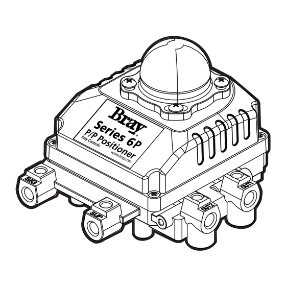
Bray Series 6P Operation and Maintenance Manual Parts and Assembly - Figure 2 COVER Auto/Manual Adjustment PILOT VALVE SPAN ADJUSTMENT DOME GEAR CONNECTOR FEEDBACK SHAFT INPUT BELLOWS ZERO ADJUSTMENT OUTPUT 1 SIGNAL IN OUTPUT 2 SUPPLY IN *Auto / Manual Adjustment is Factory... -
Page 8: Imensions
Bray Series 6P Operation and Maintenance Manual Dimensions in Inches (mm) Installation Figure 3 CAUTION 7.34 (186.5) 5.20 (132.1) When installing a positioner, please read and follow all safety instructions: • Series 6P should be used for quarter-turn valves and actuators only. -
Page 9: Bracket Information
Bray Series 6P Operation and Maintenance Manual 3. Attach the Series 6P to the bracket as shown in Bracket Information Figure 8. This sets the alignment of the main The Series 6P is supplied with a standard adjustable shaft and the center of the actuator stem. -
Page 10: Piping C Onnection
Operation and Maintenance Manual 5. Piping Connections Piping connection with actuator Series 93 Spring Return Actuator When mounting on the Bray S93 Spring Return NOTICE Actuator, OUT 1 should be connected to port A (left To avoid introducing moisture or dust, both supply... -
Page 11: A Djustment & C Alibration
Bray Series 6P Operation and Maintenance Manual Adjustment – Cam Adjustment – Span 1. If the valve actuator rotates counter-clockwise to 1. After setting the Zero Point, increase the signal open the valve on increasing air signal, the face pressure to 15 psi. Loosen the locking screw of the cam must show “RA (CCW)”... -
Page 12: Troubleshooting
NOTICE attached to a very small capacity actuator (ex: The Poppet Seat Adjuster is factory set and sealed Bray Series 92/93 size 48). In such case, install before the positioner is shipped. Do not adjust an output orifice for OUT 1 and OUT 2 per the Auto / Manual default setting (Automatic) as shown.
Need help?
Do you have a question about the 6P Series and is the answer not in the manual?
Questions and answers