Table of Contents
Advertisement
E16
Manual
Series D521
(Revision 07)
Product Manual
Original Instructions
valid for versions
D521.02
2 Relay Outputs as SPDT relays
D521.04
4 Relay Outputs (2 as SPDT relays, 2 as PhotoMOS relays)
D521.10
1 Analog Output
D521.12
2 Relay Outputs as SPDT relays + 1 Analog Output
D521.14
4 Relay Outputs (2 as SPDT relays, 2 as PhotoMOS relays) + 1 Analog Output
increased safety requirements up to SIL1
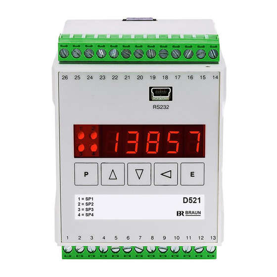
D521 Front View
Single Channel Speed Monitor
D521-Manual_EN_Rev07
for
2017_05_26
Page 1 of 31
Advertisement
Table of Contents

Related Manuals for Braun D521 series


Summary of Contents for Braun D521 series
- Page 1 Manual Series D521 (Revision 07) Product Manual Original Instructions valid for versions D521.02 2 Relay Outputs as SPDT relays D521.04 4 Relay Outputs (2 as SPDT relays, 2 as PhotoMOS relays) D521.10 1 Analog Output D521.12 2 Relay Outputs as SPDT relays + 1 Analog Output D521.14 4 Relay Outputs (2 as SPDT relays, 2 as PhotoMOS relays) + 1 Analog Output D521 Front View...
-
Page 2: Table Of Contents
Dimensions..............................25 Function diagram and connections of D521 ....................26 Connections of measuring signals to input ....................27 Connection of BRAUN sensors ......................... 28 Connection of A5S1.. with D461 to D521 ....................29 Safety Data ................................ 30 Safety Data of Measuring Chain D521-A5S0 resp. D521-D461-A5S1 ............30 Revision notes.............................. -
Page 3: Technical Specifications
Technical Specifications Design Snap-on-track plastic enclosure for 35 mm rail, field mounting enclosure (Option -G) on request. Dimensions: see chapter 7.3 Weight: standard version approx. 0.3 kg, option –G approx. 1.0 kg Installation Conditions Ambient temperature in operation: 0°C...+60°C Ambient temperature in storage: -40°C...+85°C Electrical insulation grade: I Voltage grade: I... -
Page 4: Description
Description Function The device measures the speed of rotating equipment such as turbines, compressors or ex- panders and monitors it versus setpoints and converts it into an analog output. Parameters may be set via front keyboard and display or via the RS-232 data interface. Display and Operating Elements Data-Interface RS232... -
Page 5: Measuring Principle
- 2-leads NAMUR sensors DIN 19234 (if programmed): Current level on/off >2.0 mamps / < 1,2 mamps with programmable hysteresis Sensor supply: 8 volts with 1 kOhm load resistor (incorporated). Corresponding BRAUN Sensors listed in Wiring Diagrams on page 26. 2.10 Signal Input mV-Path (millivolts) Terminal 15 Accepting low level sensors or such with superposed DC-level, or such missing the above specified V-levels. -
Page 6: Alarms
2.13 Alarms Two (optionally four) individual setpoints control an own signal output (2 as SPDT relays contacts, 2 as option with PhotoMOS relay contacts). Each with individually programmable response characteristics, and each with programmable starter. 2.14 Analog Output (D521.10, D521.12, D521.14) Output signal isolated and linear as current 0/4…... -
Page 7: Model No. Code
Model No. Code Analog Output No. of Alarms D521.02 (2 SPDT relay outputs) D521.04 (2 SPDT relay outputs + 2 PhotoMOS relay outputs) D521.10 none D521.12 (2 SPDT relay outputs) D521.14 (2 SPDT relay outputs + 2 PhotoMOS relay outputs) D521-Manual_EN_Rev07 2017_05_26 Page 7 of 31... -
Page 8: Parameters
Parameters Summary of parameters and their default values as set on delivery Param. Default Parameter Function value P00.xx Code figure, Parameter Lock, Front side Reset of Alarms P00.00 0000 Code figure 0000 New code figure 0 Front side Parameter Lock : 0: locked / 1: enabled 0000 Minimum Measuring Period (in xxxx milliseconds) 000 Starter Time Period (in xxx sec) P01.xx... -
Page 9: Setting The Parameters Via Rs232-Interface
3 Baudrate: 0 : 300 / 1 : 1200 / 2 : 9600 / 3 : 19200 / 4 : 38400 001 Device no.: 001 …125 Setting the Parameters via RS232-Interface Only possible for OEM with special interface software IS-RS232-S and adapter cable L3D01 from BRAUN. PC must have a 9pole SUB-D RS232 Interface. D521-Manual_EN_Rev07 2017_05_26... -
Page 10: Setting The Parameters Via Front Keyboard
Setting the parameters via Front Keyboard Select a parameter via its ‚name’ Pgg.ss, Principle: in that gg : Parameter-group number and ss : Step-number within the group, then display the value and alter if required. Procedure: Initiate programming phase by pressing keys together;... -
Page 11: Description Of Parameters And Their Settings
Description of Parameters and their Settings Parameter Group P00.xx Code Figure, Parameter Lock, Front side Reset of Alarms Parameter No. Description of Parameters and their Settings Meaning of Parameter Setting Range of Parameter P00.00 If the parameters are locked (see P00.02), the code figure must be entered Code Figure prior to any change of other parameters. - Page 12 Parameter Group P01.xx Measurement Configuration, Sensor Monitoring Parameter No. Description of Parameters and their Settings Meaning of Parameter Setting Range of Parameter P01.00 to P01.03: Scaling defines the relation between the input signal frequency (in terms of Scaling Hz), and the corresponding display (e.g. in RPM and decimal position required by the application).
- Page 13 Note: - Selection of Setting 0 makes Step P01.08 meaningless. - The voltage level check is only possible with Braun sensor type A5S... In this instance a signal lead break between sensor and D521 will be detected at stand still of the machine. This check requires a jumper between terminals 14 and 16.
- Page 14 Parameter Group P02.xx Display Parameter No. Description of Parameters and their Settings Meaning of Parameter Setting Range of Parameter P02.00 If the speed display uses 4 or more digits, for application reasons, the lesser LSDs on zero significant digits (LSD) may appear fluctuating. To avoid irritations by not Range: 0 ..
- Page 15 Parameter Group P03.xx Analog Output Parameter No. Description of Parameters and their Settings Meaning of Parameter Setting Range of Parameter P03.00 The high end (corresponding to 20 mamps) is programmed by the same High end of analog output terms as used in step P01.03 (e.g. in RPM). Range: 00001 ..
- Page 16 Parameter Group P04.xx Alarm SP1 Parameter No. Description of Parameters and their Settings Meaning of Parameter Setting Range of Parameter P04.00 Setpoint SP1 is programmed in the same terms (e.g. RPM) as selected for Setpoint SP1 the display of the variable in step P01.03. Range: 00001 ..
- Page 17 Parameter Group P05.xx Alarm SP2 Parameter No. Description of Parameters and their Settings Meaning of Parameter Setting Range of Parameter P05.00 Setpoint SP2 is programmed in the same terms (e.g. RPM) as selected for Setpoint SP2 the display of the variable in step P01.03. Range: 00001 ..
- Page 18 Parameter Group P06.xx Alarm SP3 Parameter No. Description of Parameters and their Settings Meaning of Parameter Setting Range of Parameter P06.00 Setpoint SP3 is programmed in the same terms (e.g. RPM) as selected for Setpoint SP3 the display of the variable in step P01.03. Range: 00001 ..
- Page 19 Parameter Group P07.xx Alarm SP4 Parameter No. Description of Parameters and their Settings Meaning of Parameter Setting Range of Parameter P07.00 Setpoint SP4 is programmed in the same terms (e.g. RPM) as selected for Setpoint SP4 the display of the variable in step P01.03. Range: 00001 ..
- Page 20 Example: Alarm SP1 as Setpoint with hysteresis "below" LED off LED on Legend Relay de-energized Relay energized alarm on alarm off Variable setpoint SP1 setpoint - hysteresis time Alarm SP1 variable < SP variable > SP variable < SP State of relay and LED, if parameter "Relay state at n >...
-
Page 21: Default Values At Delivery
Parameter Group P08.xx RS232-Data Interface Parameter No. Description of Parameters and their Settings Meaning of Parameter Setting Range of Parameter P08.00 Setting: Baud rate 300 Baud Range: 0 .. 4 1200 Baud 9600 Baud 19200 Baud 38400 Baud P08.01 "my device" No (address) Range: 001 .. -
Page 22: Installation
Installation The unit is designed for snap-on track mounting according DIN 50022. Dimensions see chapter 7.3. As a specific version, it can be supplied in a field mounting enclosure (appendix –G to model No.). D521-Manual_EN_Rev07 2017_05_26 Page 22 of 31... -
Page 23: Safety Notes For Installation And Operation
Safety Notes for Installation and Operation Safety Notes for Installation This unit has been designed and inspected according to standards DIN EN 61010-1. Observe these instructions and wiring diagrams carefully, to ensure this protection. The installation must be done only by adequately qualified personnel. 7.1.1 General Instructions Do not open the instrument. -
Page 24: Safety Notes For Sil2 Speed Applications In Hazardous Areas
Safety Notes for SIL2 Speed applications in hazardous areas 7.2.1 Monitoring the Speed Signal The barrier D461 monitors the current consumption of the sensor A5S1.. and will release an alarm in case of a fault. This provides an early warning, if a defective or non-connected sensor is detected. -
Page 25: Dimensions
Dimensions Dimensions (mm) of snap-on-track (standard) version Snap on 35 mm trail (according to DIN 50022) Dimensions of Field Mounting Enclosure (Option -G) 148 mm 4 bore holes of 4.2 mm Ø 88 mm 120 mm 3 cable conduits PG 9 160 mm D521-Manual_EN_Rev07 2017_05_26... -
Page 26: Function Diagram And Connections Of D521
Function diagram and connections of D521 D521 Terminal Display and Keys D/A-converter Analog output - mA and analog output high = Starter active (12- 24 V) Reference to starter signal Switch capability maximum 250V/2A/100W alarm SP1 Provide overload protection at inductive loads measurement Contacts shown in their de-energized... -
Page 27: Connections Of Measuring Signals To Input
Connections of measuring signals to input (Connection of BRAUN sensors see next pages) terminals supply +8V via 1kOhms 2 leads proximity sensor NAMUR or DIN 19234 screen 0 V reference active signal sources with: Signal high-level > 7 V, low-level <... -
Page 28: Connection Of Braun Sensors
Connection of BRAUN sensors marks at BRAUN cable leads terminals 2-leads proximity A4S... sensor 3-leads A4S... proximity sensor hall effect A5S... sensor screen bar cable L2A16 BO inductive sensors A2S..adaptor cable B1A003 photoelectric A1S30P reflective probe Note: The photoprobe requires marking by a high-reflex tape (U1A-006) on a clean surface. -
Page 29: Connection Of A5S1.. With D461 To D521
Sensor A5S1... BRAUN sensor contact plug terminals hazardous area non-hazardous area Note: Connect Screen to Screenbar or to Safe Ground potential marks at BRAUN cable leads D461 10 11 Signal 'Starter' D521.14 Note: Parameter P01.09 = 2 D521-Manual_EN_Rev07 2017_05_26 Page 29 of 31... -
Page 30: Safety Data
Safety Data Safety Data of Measuring Chain D521-A5S0 resp. D521-D461-A5S1 Note: PFD values below are valid only if „Safety Notes for Installation and Operation“ are observed and maintained. PFD values of D521 apply to relay output SP1 and analog output. PFD Values at Tproof Tproof Tproof... -
Page 31: Revision Notes
Chapter 8 for Safety of Measuring Chain D521-A5S0 resp. D521-D461-A5S1 added 30.03.2016 Description of parameter P01.05 modified 26.05.2017 Change to Bookmark Format Qualität zertifiziert nach ISO 9001 D 71334 Waiblingen-Hegnach Esslinger Str. 26 Tel.: +49 (0)7151/956230 Fax: +49 (0)7151/956250 E-Mail: info@braun-tacho.de Internet: www.braun-tacho.de D521-Manual_EN_Rev07 2017_05_26 Page 31 of 31...
Need help?
Do you have a question about the D521 series and is the answer not in the manual?
Questions and answers