
Related Manuals for Braun MOVIPORT C118 Series


Summary of Contents for Braun MOVIPORT C118 Series
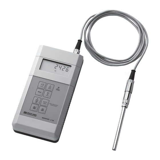
- Page 1 Universal Hand Held Tachometer MOVIPORT C118 Series Manual Hand Held Tachometer C118 + Cable SAK-2m + Sensor A1S30P95...
-
Page 3: Table Of Contents
Universal Hand Held Tachometer MOVIPORT C118 Series Manual Contents Page C118 Versions and Accessories ................ 2 Specifications ....................3 Operational Elements ..................4 Short Form Instructions to Operation ............... 5 Sensors and Cables fitting the C118 ..............6 Sensor Selection and Target Marking Directions ..........7 Instrument Connections .................. -
Page 4: C118 Versions And Accessories
Scope of the MOVIPORT C118 Series ̶ Overview Ordering No. Equipment comprising C118BS Standard Equipment with battery-powered Instrument C118, Optosensor A1S30P95, plug-in connector cable SAK-2m, marking aids, carrying case C118.1BS Instrument with RS232 Data Interface and adapter cable L3D01, other equipment as under C118BS C118.2BS... -
Page 5: Specifications
Specifications Measuring Function Principle Pulse distance measurement with automatically extended number of periods, as determined by a programmable* minimum measuring time allowance. Low end of operating range programmable*, high end = 100 kHz. Accuracy + 0.05 % + 1 in last active digit. Special Function (SF) provides continuous totalizing of input pulses. -
Page 6: Operational Elements
Operational Elements Jack to supply Turning knob to preset the unit U1H008 maximum input sensitivity (C118.2 and C118.3 only) 2x BNC jacks for pulse output Input socket to analog output sensor connection Socket for Data interface Display reading measurements with their time reference, operating mode, pro- gram Step No and its... -
Page 7: Short Form Instructions To Operation
Short Form Instructions to Operation Further explanation on page FIX Operation Mode Immediate direct tachometer function. Range 30 / min up to 100,000 / sec, no programming at all valid for 1 mark per revolution. required Display with automatic decimal point: Last digit = 0.x Details on page 13. -
Page 8: Sensors And Cables Fitting The C118
Sensors and Cables fitting the C118 Application Characteristics Part No. Optoelectronic Sensor as standard, 95 mm shaft A1S30P95 * (part of equipment C118BS, C118.1BS, C118.2BS and C118.3BS). same, with short shaft 35 mm. A1S30P35 * Optosensor, with increased light intensity, with 5m A1S36P95-5m cable firmly attached (part of C118.2BP and C118.3BP). -
Page 9: Sensor Selection And Target Marking Directions
Notes to sensor selection and how to mark the target Optoelectronic type sensors A1S30P95, There is hardly another type of sensors fitting better to var- the standard for ying applications as the non-contact optoelectronic versions optoelectronic sensing do. The target is fast and easily prepared. The automatic signal conditioning, incorporated with the C118, accepts a line of paint, a hole, or a screw, or a blade as a mark. - Page 10 Sensors with function principle based on magnetic field Magnetic type Typical application is the speed detection of a rotating gear sensors detect wheel, or similarly profiled part, with steel as material. May rotating steel be used under oil, or water, or within a greasy ambiance. profiles, even under oil or Sensing distance (clearance) typical 0.5 …2 mm.
-
Page 11: Instrument Connections
Operating the C118 Connections Analog and Pulse Output 2 front side BNC jacks provide the analog output and the Connecting the analog output or pulse output. Available is a ready-made cable U1H014, with BNC connectors on both ends. pulse output Sensor Input Sensor The standard reflection type sensor A1S30P can be pushed... -
Page 12: Power Supply
Power Supply Mostly used, for best flexibility, are batteries (MN1500x4) Powered by or re-chargeable cells (IECR6). They are inserted into the batteries, cells, battery case underneath. or from mains by Further, the supply unit U1H008 may be used. Its output supply unit cable will be plugged into the front side metallic jack. -
Page 13: Input Response
Input Signal Conditioning In its normal mode, the input of the C118 automatically Automatic signal adapts to the characteristics and size of the input signal. It conditioning = adjusts the signal gain, and eliminates erratic pulses, as fre- normal mode quently generated in photoelectric sensing by scratches and stains on the target surface. -
Page 14: Max/Min Memory
No reliable measurement can be expected unless the input signal is clearly accepted! indispensable Note: pre-condition The input indicator may still be operational with the power to reliable measurements supply no longer adequate. MAX/MIN/AVG Function The C118 detects and memorizes the highest (MAX) and MAX/MIN/AVG the lowest (MIN) measurement within a controlled period memorizing... -
Page 15: Fix / Var Operation Modes
Operating Modes FIX and VAR FIX = straight This is one of the facilities making the C118 that much useful. Select between both modes by actuating the tachometer FIX/VAR key. VAR mode is indicated by a sign in the VAR = using the display. -
Page 16: Programming Procedure And List Of Steps
Programming the C118 List of Program Steps (effective only in VAR mode) Step Function handled Page minimum measuring time, determines sequence (by steps) maximum measuring time, determines low speed (by steps) Computing factor: multiplying mode = parameter 0 dividing mode = parameter 1 Computing factor: number of factor decimals Computing factor:... -
Page 17: Parameter Functions Shortest And Maximum Measuring Time Allowance
Programmable Characteristics – Parameter Functions (effective only in VAR mode) Minimum Measuring Time Allowance Step No. 00 All rate measurements are based on a time interval meas- minimum urement over a (automatically varying) number of input measuring time signal pulses. A programmable minimum measuring period allowance, thus will be maintained, automatically including more and determines... -
Page 18: Computing (Scaling) Factor
Computing (scaling) factor Determining the relation between One of the most fascinating facilities of the C118. It con- verts the measured signal frequency into readings in any measurement required engineer unit, introducing a conversion factor, in a and reading multiplying or dividing way. The multiplying mode increases the measured value (speed) Step No. -
Page 19: Analog Output
Notes: Do not select more decimals than necessary! If the high resolution thus achieved exceeds the stability of the varia- ble, and the repeatability of the input signal, the last digits in display and analog output necessarily will fluctuate, and be useless. -
Page 20: Automatic Power Off
Automatic Power Shut-Off Step No. 08 To save battery capacity, the C118 can be automatically Automatic Switch shut off, when idling for 10 min. Power Off Step 08 enables this function by its parameter: 0 = function disabled 1 = function enabled Input Frequency Pre-Divider Step No. -
Page 21: Display Of Totals
Parameters set on delivery (default values) Step No. Function Value Minimum Time Allowance 0.50 s Maximum Time Allowance 8.00 s Computing Factor Mode 0 (multiplying) decimals ------. (none) numerical 000001 Display decimals ------. (none) Analog Output high end 010000 low end 000000 Automatic Power off 1 (active) -
Page 22: Notes To Optional Functions Of C118 Data Interface Rs232 At C118.1 And C118.3
Serial Data Interface General Characteristics Mode: RS232, without handshake leads. 4800 baud, 8 bits, no parity. Data handling Communication provided The interface provides results from all type measurements performed in the C118. It uses its own protocol: the transmission must be requested, and any request can call for one type of measurement only. - Page 23 Note: STX, ETX, CR are not to be understood as a sequence of Important Note capitals, but as ASCII signs: frequent cause STX (start of text), in HEX code = 02 of failures ETX (end of text), in HEX code = 03 CR (carriage return) in HEX code = 0D Connection cable L3D01 and Data Port Wiring of...
- Page 24 4.2017 D 71334 Waiblingen, Esslinger Str. 26 Phone: +49 (0)7151/956230 Fax: +49 (0)7151/956250 E-Mail: info@braun-tacho.de Internet: www.braun-tacho.de Manual C118 EN Rev04 04.2017...
Need help?
Do you have a question about the MOVIPORT C118 Series and is the answer not in the manual?
Questions and answers