Table of Contents
Advertisement
Quick Links
Advertisement
Table of Contents

Summary of Contents for Inova SV 125
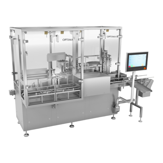
- Page 1 OPTIMA GROUP pharma GmbH Schwaebisch Hall / Germany Translation of the original operating manual Operating Manual Fully Automatic Filling And Closing Machine For Syringes SV 125 Customer: AP Pharma Inc., USA Machine no.: 4016589 Year of manufacture: 2011...
- Page 2 OPTIMA GROUP pharma GmbH Schwaebisch Hall / Germany Otto--Hahn--Straße 1 D -- 74523 Schwäbisch Hall Phone.: +49 791 9495--0 Fax: +49 791 9495--2680 Internet: www.optima--group--pharma.de E OPTIMA GROUP pharma 03/2013 This documentation is protected by copyright. All rights reserved. No part of this documentation may be translated, reproduced, stored in a retrieval system, or transmitted, in any form or by any means -- graphic, electronic or mechanical, in- cluding photocopying, recording, taping -- without the prior permission of the pub-...
-
Page 3: Table Of Contents
Contents SV 125 4016589 Contents Safety regulations ....... . 1- -1 Duties and liability . - Page 4 Contents SV 125 4016589 Maintenance and servicing ........
- Page 5 Contents SV 125 4016589 Storage and conservation ........
- Page 6 Contents SV 125 4016589 Functional description ........
- Page 7 Contents SV 125 4016589 Operation ........
- Page 8 Contents SV 125 4016589 5.2.23 Main -- Menu ............
- Page 9 Contents SV 125 4016589 5.2.45 Format input -- Filling curve vacuum (piston pumps) [1/4] ....5--89 5.2.46 Format input -- Filling curve vacuum (piston pumps) [2/4] .
- Page 10 Contents SV 125 4016589 5.2.63 Format input -- Teach servo axis insertion tube ......
- Page 11 Contents SV 125 4016589 5.2.84 Information -- Tub error code insertion tube ......
- Page 12 Contents SV 125 4016589 Operating modes ..........
- Page 13 Contents SV 125 4016589 7.1.2.8 Insertion rod holder stoppers - - (size part 14) ........
- Page 14 Contents SV 125 4016589 Cleaning and maintenance ......9- -1 Cleaning ........... . .
- Page 15 Contents SV 125 4016589 9.4.5 Maintenance plan interval 1000 operating hours ......9--21 9.4.5.1 Lubricate pump drive .
- Page 16 Contents SV 125 4016589...
- Page 17 Notes SV 125 4016589 Notes This operating manual is designed to familiarize the operator with the mode of function the operation the safety instructions and the maintenance of the machine. Storage Keep the operating manual next to the machine at all times!
- Page 18 Notes SV 125 4016589 Danger classes The table below indicates the symbols and signal words as well as the dangers and possible effects to which they refer. Symbol Signal word Signal color Definition Effects DANGER! Imminent danger Death or severe in-...
- Page 19 Notes SV 125 4016589 Explanation of terms Term Explanation Safety Devices that indirectly protect from danger areas (e.g. light grids, devices door contact switches). Protection Devices that protect from intervention into the danger areas (e.g. guard doors, casings). devices Protective...
- Page 20 Notes SV 125 4016589 Version 1.0 Page 4...
-
Page 21: Safety Regulations
Safety regulations SV 125 4016589 Safety regulations This operating manual includes the most important information necessary to oper- ate the machine in a safe manner. Duties and liability 1.1.1 Information and instructions given in the operating manual The basic requirement for handling the machine in a safe manner and for the fault-- free operation of this machine is knowledge of the basic safety instructions and safety regulations. - Page 22 Safety regulations SV 125 4016589 Danger classes The table below indicates the symbols and signal words as well as the dangers and possible effects to which they refer. Symbol Signal word Signal color Definition Effects DANGER! Imminent danger Death or severe in-...
-
Page 23: Warranty And Liability
Safety regulations SV 125 4016589 1.1.3 Warranty and liability Our “General Conditions of Sale and Delivery” apply throughout. These will be available to the plant operator at the latest upon conclusion of the contract. Any warranty or liability claims pertaining to persons and property damage are ex-... -
Page 24: Behavior For Safe Operation
Safety regulations SV 125 4016589 1.1.4 Behavior for safe operation The machine provides operational reliability if used as intended. In case of im- proper use danger to person or damage to property can arise. Please abstain from any method of operation that raises doubt to safety. - Page 25 Safety regulations SV 125 4016589 Risk of tripping! Blade hazard for hands and limbs Entanglement of hands and limbs Entanglement of hands and limbs Automatic start Wear protection goggles Wear gloves Read operating manual NOTE Persons with pacemakers are not allowed in this area! Do not drill! Version 1.0...
-
Page 26: Intended Use
Safety regulations SV 125 4016589 1.1.5 Intended use The machine is intended only for the use defined in chapter 4.1.1, page 4.1.1. Intended use also includes: compliance with all instructions and information in the operating manual and compliance with the inspection and maintenance work. -
Page 27: Safety Devices And Protective Equipment
Safety regulations SV 125 4016589 Safety devices and protective equipment 1.2.1 Installed devices For the protection of the operating personnel, the environment and the machine, the machine is equipped with the following safety devices and protective equip- ment: POWER supply disconnecting device (main switch), lockable. -
Page 28: Power Supply Disconnecting Device
Safety regulations SV 125 4016589 Mode of procedure Precondition is machine standstill. 1.2.2.1 POWER supply disconnecting device Set POWER supply disconnecting device to OFF ”0”. The display must be blank. 1.2.2.2 Compressed air supply disconnecting device Turn off compressed air supply disconnecting device. -
Page 29: Danger And Information Signs
Safety regulations SV 125 4016589 1.2.3 Danger and information signs The danger and information signs on the machine must not be removed must be clearly legible. Check them regularly. NOTE Order missing or illegible danger and information signs via spare parts catalog and attach them to the respective position. -
Page 30: Duties Of The Plant Operator
Safety regulations SV 125 4016589 Duties of the plant operator 1.3.1 Warranty and liability WARNING! A defective or badly maintained machine increases the risk of acci- dents. Only operate the machine in a technically faultless condition. The machine has been built in accordance with state--of--the--art technology, yet dangers can emanate from the machine. -
Page 31: Personnel Requirements
Safety regulations SV 125 4016589 The operating personnel must have read and understood the operating manual. Comply with the instructions in the manual and keep the manual ready to hand at the machine at all times. Instruct the operating personnel in accident prevention and environmental protec- tion routines. -
Page 32: First Aid
Safety regulations SV 125 4016589 Immediately report and eliminate any detected fault or damage. Interrupt the production until the problem has been eliminated. In case of maintenance or repair work use suitable measures to prevent others approaching the work area (chain locks and danger signs). -
Page 33: Maintenance And Servicing
Safety regulations SV 125 4016589 Maintenance and servicing Perform the prescribed adjusting, maintenance and inspection work within the stip- ulated time period. NOTE If repairs should be performed on the machine, please contact OPTIMA GROUP pharma; this ensures a competent and professional repair. -
Page 34: Constructional Changes To The Machine
Safety regulations SV 125 4016589 DANGER! The compressed air supply disconnecting device disconnects the com- pressed air energy required for machine operation and releases the compressed air. The machine is vented. When the compressed air supply disconnecting device is turned off, hazardous pneumatic pressure might still be present. -
Page 35: Cleaning
Safety regulations SV 125 4016589 1.5.2 Cleaning The machine is not designed for wet cleaning. Do not use a water jet to clean the machine. Do not use solvents or other aggressive or flammable substances to clean the ma- chine. Always comply with the manufacturer’s instructions. -
Page 36: Information Regarding Electrical Energy
Safety regulations SV 125 4016589 Information regarding electrical energy DANGER! Electric shocks can cause severe burns and life--threatening injuries. Electrical equipment can be energized. Before working on electrical equipment turn off the POWER supply dis- connecting device and disconnect the mains supply of the control cab- inet. -
Page 37: Dangers From Electrical Power
Safety regulations SV 125 4016589 Safety devices may be removed only after the machine has come to a standstill and if the machine has been secured against being put back into operation (e.g. pad- lock on the POWER supply disconnecting device). -
Page 38: Residual- -Current- -Operated Protective Devices (Rcd)
Safety regulations SV 125 4016589 Residual- -current- -operated protective devices (RCD) NOTE In the control unit of the machine electronic equipment with controlled semi--conductors and noise filters is used that is not compatible with all types of residual--current--operated protective devices (RCD). -
Page 39: General Information About Risks
Safety regulations SV 125 4016589 General information about risks 1.8.1 Residual risk At the time of delivery the machine is state of the art. However, a residual risk for persons and the machine remains, as the machine is operating with hazardous mechanical movements, live voltages and currents. -
Page 40: Dangers From Residual Energy
Safety regulations SV 125 4016589 1.8.2 Dangers from residual energy CAUTION! Individual stations of the machine are still pressurized even after EMERGENCY STOP or when the guard doors are open! Turn off the compressed air supply disconnecting device before per- forming maintenance and cleaning work on the machine. -
Page 41: Safety Measures During Normal Operating Mode
Safety regulations SV 125 4016589 1.8.5 Safety measures during normal operating mode Operate the machine only if all safety devices are installed and fully operable. Watch out for loose parts and remove them, if necessary. Vibrations can cause loose or insufficiently attached parts to fall down. -
Page 42: Harmful Fumes
Safety regulations SV 125 4016589 1.8.6 Harmful fumes WARNING! When processing products, from which a health hazard for the operat- ing personnel can emanate, the plant operator must take the requisite safety precautions. Harmful fumes can escape during operation of the machine. -
Page 43: Transport, Installation And Connection
Transport, installation and connection SV 125 4016589 Transport, installation and connection Items included in the delivery Check the completeness of the delivery against the packing list! Any missing parts or damage as a consequence of deficient packing or due to transport must be immediately communicated in writing to the forwarder, the insur- ance company and OPTIMA GROUP pharma. -
Page 44: Preparations For Transport
Transport, installation and connection SV 125 4016589 2.2.2 Preparations for transport Observe the transport information on the packaging. Disconnect the machine from all energy supply systems and disconnect all lines to other machines, facilities or devices. Close open line ends. -
Page 45: Transport Drawing
Transport, installation and connection SV 125 4016589 2.2.5 Transport drawing The tines must be positioned between the feet of the machine. The tines must protrude on the other side of the machine. Storage and conservation To keep an unused machine operable over a long period of time, observe the fol- lowing instructions: The storage room must be clean and dry. -
Page 46: Installation And Connection
Transport, installation and connection SV 125 4016589 Installation and connection DANGER! Electric shocks can cause severe burns and life--threatening injuries. Risk of fatal injury from electrical current and other energies. Only qualified personnel are allowed to connect the machine. CAUTION! The danger areas in the transfer areas and on the machine have to be safeguarded by the plant operator. - Page 47 Transport, installation and connection SV 125 4016589 DANGER! Electric shocks can cause severe burns and life--threatening injuries. Ensure that the numbers on the plugs of the power supply cables match those on the sockets on the control cabinet. Check that the motors turn in the correct direction!
-
Page 48: Dismantling
Transport, installation and connection SV 125 4016589 Dismantling DANGER! Risk of fatal injury from electrical current and other energies. Disconnect the machine from the energy supply prior to removal. Depressurize all pressurized systems. NOTE Dismantling must be performed by qualified personnel. -
Page 49: Description Of The Machine
Description of the machine SV 125 4016589 Description of the machine Views of the machine Top view Version 1.0 3--1... -
Page 50: Workplace
Description of the machine SV 125 4016589 Workplace Version 1.0 3--2... -
Page 51: Guard Doors
Description of the machine SV 125 4016589 Guard doors NOTE The operator is separated from the danger area of the machine by guard doors and covers. Guard door 7 Guard door 6 Guard door 5 Guard door 4 Guard door 1... -
Page 52: Danger Areas
Description of the machine SV 125 4016589 Danger areas WARNING! In the areas marked with this danger sign a danger of crushing exists from moving parts at the machine and at the infeed and discharge. Version 1.0 3--4... - Page 53 Description of the machine SV 125 4016589 DANGER! Electric shocks can cause severe burns and life--threatening injuries. Electrical equipment can be energized. Before working on electrical equipment turn off the POWER supply dis- connecting device and disconnect the mains supply of the control cab- inet.
-
Page 54: Emergency Stop Buttons
Description of the machine SV 125 4016589 EMERGENCY STOP buttons On operator panel On machine Version 1.0 3--6... -
Page 55: Interfaces And Connections
Description of the machine SV 125 4016589 Interfaces and connections Connection power supply Connection compressed air supply Version 1.0 3--7... -
Page 56: Identification Of The Machine
Description of the machine SV 125 4016589 Identification of the machine 3.7.1 Nameplate 4016588 2011 4016588 SV 125 4016589 2011 4016589 NOTE A respective nameplate is also located on the control cabinet of the machine. Version 1.0 3--8... -
Page 57: Technical Specifications
Description of the machine SV 125 4016589 Technical specifications 3.8.1 General data Length (with TRB): approx. 4374 mm Width: approx. 1809 mm Height: approx. 2110 mm Working height: approx. 1120 mm ± 15 mm Weight: SV 125 Control cabinet approx. 1880 kg approx. -
Page 58: Formats
Description of the machine SV 125 4016589 3.8.3 Formats Format Nest size [items] 1 ml 3.8.4 Output The maximum output of the machine is 10.000 syringes/h. The output depends on the syringe size, on the fill volume and on the specific qualit- ies and the viscosity of the product. -
Page 59: Machine Accessories
Description of the machine SV 125 4016589 Machine accessories Standard accessories are: Operating manual Operating manual of sub--supplied parts Spare parts catalog Wear parts list Check the tools and auxiliary devices for completeness. Version 1.0 3--11... - Page 60 Description of the machine SV 125 4016589 Version 1.0 3--12...
-
Page 61: Structure And Function
Structure and function General 4.1.1 Intended use of the machine The fully automatic syringe filling and closing machine type SV 125 exclusively is designed to fill and close syringes in nests. The machine is intended for use in sterile rooms. WARNING! Any use that extends beyond this is valid as being a non--intended use. -
Page 62: General Description
SV 125 4016589 4.1.3 General description The SV 125 operates in cycles. Five syringes are filled and sealed per machine cycle. The machine consists of the following main assemblies: Stable base mounting with height adjustable spindle feet Closed machine subframe with stainless steel casing Polycarbonate machine guarding. -
Page 63: Mode Of Operation
Structure and function SV 125 4016589 4.1.4 Mode of operation The work steps described below represent a processing routine in chronological order. The tubs are fed manually to the Tyvek Removal Box via infeed chute. The operator pulls off the Tyvek--foil manually and removes the Tyvek--inlay sheet on the tub. -
Page 64: Functional Description
Structure and function SV 125 4016589 Functional description 4.2.1 Overview 8,9,11,12 Version 1.0 4--4... -
Page 65: Infeed Chute
Structure and function SV 125 4016589 4.2.2 Infeed chute (1) The infeed chute (A) transports the tub to the Tyvek Removal Box. The operator places the tub on the infeed chute by hand. 4.2.3 Tub support (2) In the Tyvek Removal Box the operator has to put the tub manually into the tub sup- port (B). -
Page 66: Transport Belt
The operator takes the tub out of the Tyvek Removal Box and places it on the trans- port belt (D). The transport belt transports the tubs to the nest pick--up station of the SV 125. Tub--stopper 1 (infeed gate) (E) separates the tubs on the transport belt. - Page 67 Structure and function SV 125 4016589 Tub stopper 2 (F) stops the tubs at the nest pick--up station. Sensor Tub present (G) checks, if a tub is present at tub stopper 2. Tub stopper 3 (H) stops the tubs at the nest insertion position.
-
Page 68: Nest Pick--Up Station
Structure and function SV 125 4016589 4.2.5 Nest pick- - up station (4) The nest pick--up station (J) takes the nest out of the tub and puts it down on the nest centering device of the X--Y--table. When the nest has been taken out of the tub, tub stopper 2 releases the tub for further transport and the empty tub is transported on to the nest insertion position via transport belt. -
Page 69: Y--Table
Structure and function SV 125 4016589 4.2.6 X-Y- - table (5) The servo driven X--Y--table (K) transports the syringes to the filling station and to the stopper insertion station. After nest transfer, the X--Y--table performs a shaking movement to fix the syringes. -
Page 70: Dosing Station
Structure and function SV 125 4016589 4.2.8 Dosing station (7) The rotary piston pumps of the dosing station (M) pump the product that is to be filled in the specified quantity to the filling needles. The dosing quantity is adjusted on the operator panel. -
Page 71: Filling Station
Structure and function SV 125 4016589 4.2.9 Filling station (8) At the filling station the filling needles (N) are lowered down into the syringe barrels. The syringes are filled in rows. Sensor Overload filling needle (O) checks, if a filling needle has been pushed out of the holder. -
Page 72: Filling Station With Vacuum Filling
Structure and function SV 125 4016589 4.2.10 Filling station with vacuum filling (9) In addition to the conventional filling, the machine is equipped with a vacuum filling system. The filling heads of the vacuum chamber (P) are placed on the syringes. The va- cuum valves open and the vacuum lines and the syringes are evacuated via va- cuum tank. -
Page 73: Sensor Syringe Too High After Filling
Structure and function SV 125 4016589 4.2.10.1 Sensor Syringe too high after filling NOTE The sensor only operates during vacuum filling. CAUTION! Laser class 2 When working with or near the laser wear protection goggles. Do not stare into the laser beam. -
Page 74: Stopper Sorter And Stopper Lanes
Structure and function SV 125 4016589 4.2.11 Stopper sorter and stopper lanes (10) The sorting bowl (S) transports the stoppers to the stopper lanes in correct position. The operator must fill the sorting bowl manually via chute (T). The stopper lanes (U) transport the stoppers to the transfer piece. -
Page 75: Filling The Stopper Lanes With Stoppers
Structure and function SV 125 4016589 4.2.11.1 Filling the stopper lanes with stoppers The filling of the stopper lanes with stoppers, e.g. after format changeover, must be performed gradually and with reduced speed of the stopper lanes. Reduce the preset value of the speed of the stopper lane by half. -
Page 76: Stopper Insertion Station
Structure and function SV 125 4016589 4.2.12 Stopper insertion station (11) The stopper insertion station inserts the stoppers into the syringes. The stopper pins press the stoppers from the transfer piece into the stopper turning device (W), which then swivels over the insertion tubes. In the next step the inser- tion rods (X) press the stoppers into the insertion tubes. -
Page 77: Sensors Of The Stopper Insertion Station
Structure and function SV 125 4016589 4.2.12.1 Sensors of the stopper insertion station Sensor Stopper upside down in stopper turning device (Z) checks, if the stop- pers are correctly orientated. If a stopper is not correctly positioned, the stopper pin presses it into the stopper turning device too far. -
Page 78: Vacuum--Stopper Insertion Station
Structure and function SV 125 4016589 4.2.13 Vacuum- - stopper insertion station (12) In addition to the conventional stopper insertion system, the machine is equipped with a vacuum stopper insertion system. The vacuum stopper insertion system consists of: 5 Insertion rods (format dependent) - Page 79 Structure and function SV 125 4016589 After venting, the vacuum insertion rod holder moves up and the table moves to the next position. When the stopper insertion process has ended, the valves of the vacuum line are closed and the vacuum insertion rod holder is vented, to release the filling heads from the syringes.
-
Page 80: Sensor Syringe Too High After Stopper Insertion
Structure and function SV 125 4016589 4.2.13.1 Sensor Syringe too high after stopper insertion. NOTE The sensor only operates during vacuum stopper insertion. CAUTION! Laser class 2 When working with or near the laser wear protection goggles. Do not stare into the laser beam. -
Page 81: Evacuation Station
Structure and function SV 125 4016589 4.2.14 Evacuation station (13) The vacuum pump for filling (AE) and the vacuum pump for stopper insertion (AF) evacuate the respective vacuum tanks. Vacuum tank for vacuum stopper insertion (AG). Vacuum tank for vacuum filling (AH). - Page 82 Structure and function SV 125 4016589 After the vacuum valves have been opened (AI), the remaining air is drawn out of the syringes and vacuum lines. Vacuum sensors (AJ) monitor the values that have been preset on the operator panel.
-
Page 83: Nest Insertion Position
Structure and function SV 125 4016589 4.2.15 Nest insertion position (14) The X--Y--table transports the nest with the filled and closed syringes back to start- ing position. The nest pick--up device takes the nest out of the centering plate of the X--Y--table and on the nest insertion position places the nest in the empty tub. -
Page 84: Discharge
Structure and function SV 125 4016589 4.2.16 Discharge (15) The transport belt (AO) transports the tubs on to the downstream machine. 4.2.17 Particle counting tube The particle counting tubes (AP) monitor the atmosphere in the machine. The cus- tomer evaluates the detected values. -
Page 85: Airborne Germ Collectors
Structure and function SV 125 4016589 4.2.18 Airborne germ collectors The airborne germ collectors that are positioned on the supports (AQ) monitor the clean room conditions in the machine. The customer evaluates the detected val- ues. The airborne germ collectors are not represented in the overview on page 4--4. - Page 86 Structure and function SV 125 4016589 Version 1.0 4--26...
-
Page 87: Operation
Operation SV 125 4016589 Operation Control elements on the operator panel Touch screen Indicates alarms, messages and instructions. It is operated by touching the represented control and input fields. EMERGENCY STOP The button serves to stop the machine immediately in event of danger. - Page 88 Operation SV 125 4016589 Interface connection The Ethernet--interface connection is located on the bottom side of the oper- ator panel. Socket for jog cable The socket is located on the bottom side of the operator panel. Version 1.0 5--2...
-
Page 89: Screens
Operation SV 125 4016589 Screens 5.2.1 General information NOTE The displayed screens are examples. Some of the control and input fields are only displayed for a user with full access rights. The values that might be indicated are not representative. -
Page 90: Start Screen
Operation SV 125 4016589 5.2.2 Start screen After turning on the POWER supply disconnecting device the Start screen is dis- played. The user can log in or log out. Control field Function The user is logged out. Screen Log in is called up. - Page 91 Operation SV 125 4016589 Control field Function Screen Main screen is called up. Screen Info OPTIMA GROUP pharma is called up. Version 1.0 5--5...
-
Page 92: Info Optima Group Pharma
Operation SV 125 4016589 5.2.3 Info OPTIMA GROUP pharma Address data of the company OPTIMA GROUP pharma GmbH are displayed. Control field Function The Start screen is called up. Version 1.0 5--6... -
Page 93: Clean Screen
Operation SV 125 4016589 5.2.4 Clean screen Touch control field on the Start screen. The surface of the screen can be cleaned. When the cleaning has ended, the Start screen is displayed automatically. NOTE Do not use solvents or other aggressive substances to clean the screen. -
Page 94: Software
Operation SV 125 4016589 5.2.5 Software Touch control field on the Start screen. Information about the software is displayed. Machine software Display of the current version of the machine program. Display software Display of the current version of the display program. -
Page 95: Log In
Operation SV 125 4016589 5.2.6 Log in Touch control field on the Start screen. The user can log in or change his password. Log in Touch control field Enter the user name on the keyboard. Touch control field on the keyboard to take over the entry. - Page 96 Operation SV 125 4016589 Changing the password Touch control field Touch control field Enter the new password on the keyboard. The password must consist of at least 3 characters. Touch control field on the keyboard to take over the entry.
-
Page 97: Security -- Menu
Operation SV 125 4016589 5.2.7 Security - - Menu Touch control field on the Start screen. The submenus of the password administration can be selected. Control field Function Screen Security - - Code screen is called up. Screen Security - - Code function is called up. -
Page 98: Security -- Code Screen [1/2]
Operation SV 125 4016589 5.2.8 Security - - Code screen [1/2] Touch control field on screen Security - - Menu. The assignment of the screens to the individual user groups is displayed and can be changed. Changing the assignment of a screen Touch the input field of the screen which should be assigned to another user group. -
Page 99: Security -- Code Screen [2/2]
Operation SV 125 4016589 5.2.9 Security - - Code screen [2/2] Touch control field on screen Security - - Code screen [1/2]. The assignment of the screens to the individual user groups is displayed and can be changed. Changing the assignment of a screen Touch the control field of the screen which should be assigned to another user group. -
Page 100: Security -- Code Function [1/2]
Operation SV 125 4016589 5.2.10 Security - - Code function [1/2] Touch control field on screen Security - - Menu. The individual user groups can be assigned to various functions. Shut down (operator panel) The system is shut down. Reset counter (production) The production counter is reset. - Page 101 Operation SV 125 4016589 Reset alarm status Screen Alarm - - Status list is reset. Reset alarm history Screen Alarm - - History is reset. Set date/time Date and time can be set. Print screen Screens can be printed. Performance store The values of the performance setting can be copied into a format.
-
Page 102: Security -- Code Function [2/2]
Operation SV 125 4016589 5.2.11 Security - - Code function [2/2] Touch control field on screen Security - - Code function [1/2]. The individual user groups can be assigned to various functions. Teach- -in axis Teach--in of the axes can be performed. - Page 103 Operation SV 125 4016589 Changing the assignment of a function Touch the input field next to the function whose assignment should be changed. With “all users” the function can be assigned to all user groups. The function is assigned to a certain user group by touching the input field again. After user level P, the user levels start again from ”all users”.
-
Page 104: Security - - Code [Help]
Operation SV 125 4016589 5.2.11.1 Security - - Code [help] Touch control field on screens Security - - Code screen or Security - - Code function. Information about the individual user groups is displayed. Control field Function The machine drive is switched off. -
Page 105: Security -- Parameter
Operation SV 125 4016589 5.2.12 Security - - Parameter Touch control field on screen Security - - Menu. The minimum number of characters of which a password must be composed can be set. 3 characters are preset. Changing the password minimum length Touch input field. -
Page 106: Security -- User Account
Operation SV 125 4016589 5.2.13 Security - - User account Touch control field on screen Security - - Menu. Existing user accounts can be changed and new user accounts can be defined. Defining a new user account Touch input field User number. - Page 107 Operation SV 125 4016589 Activate or deactivate option User cannot change password by touching the check box. If the option is activated, the user is not authorized to change his password. Options Change password at next log in and User cannot change pass- word cannot be activated at the same time.
- Page 108 Operation SV 125 4016589 Activate or deactivate the user groups to which the user should be assigned by touching the respective field Security code. Several user groups can be activated. Touch control field to save the user who has been newly defined.
-
Page 109: Security -- User Password
Operation SV 125 4016589 5.2.14 Security - - User password Touch control field on screen Security - - User account. A new password can be defined for the user account that has been defined on screen Security - - User account. - Page 110 Operation SV 125 4016589 Control field Function Entry of the new password. Entry of the new password for confirmation. Saves the newly defined password. The machine drive is switched off. The previous screen is called up. Version 1.0 5--24...
-
Page 111: Security - - User Account [Help]
Operation SV 125 4016589 5.2.14.1 Security - - User account [help] Touch control field on screen Security - - User account. The designations of the individual user groups (A--P) are displayed and can be changed. Changing the designation of a user group Touch the input field next to the user group whose designation should be changed. -
Page 112: Main Screen 1
Operation SV 125 4016589 5.2.15 Main screen 1 Touch control field on the Start screen. The following information is displayed: Pending error messages Date and time Format: Current format number and current format name. System [%] System speed as percent of the maximum speed. - Page 113 Operation SV 125 4016589 User User name Name Full name of the user who is logged in. Tubs complete Total number of processed tubs. Syringes complete Total number of processed syringes. Batch no. Display of the batch number. The display is continuously updated.
- Page 114 Operation SV 125 4016589 Control field Function Screen Main - - Menu is called up. The infeed gate is opened or closed. The nest processing is completed, then the nest is transported out. Screen Performance is called up. The previous screen is called up.
-
Page 115: Main Screen 2
Operation SV 125 4016589 5.2.16 Main screen 2 Touch control field on Main screen 1. The following information is displayed: Pending error messages Date and time The display is continuously updated. Control field Function Scrolls up the list of error messages. - Page 116 Operation SV 125 4016589 Control field Function Alarms / messages are reset. The machine drive is switched off. The processing of the nest is aborted and the nest is transported out. The previous screen is called up. Version 1.0 5--30...
-
Page 117: Performance [1/2]
Operation SV 125 4016589 5.2.17 Performance [1/2] Touch control field on the Main screen. The working speeds of the following drives are displayed and can be adjusted: Speed sorter [%] Speed of the stopper sorting bowl. Speed linear track [%] Speed of the stopper infeed rails. - Page 118 Operation SV 125 4016589 Changing the working speed Touch the input field of the working speed that should be changed. Enter the new working speed on the keyboard. Touch control field on the numeric keypad to take over the entry.
- Page 119 Operation SV 125 4016589 5.2.18 Performance [2/2] Touch control field on screen Performance [1/2]. The working speeds of the following drives are displayed and can be adjusted: System speed [%] Entry of the speed of the main drive. The speeds are entered as percent value of the maximum speed.
- Page 120 Operation SV 125 4016589 Changing the working speed Touch the input field of the working speed that should be changed. Enter the new working speed on the keyboard. Touch control field on the keyboard to take over the entry. NOTE The entered speeds are not saved permanently.
-
Page 121: Alarm -- Menu
Operation SV 125 4016589 5.2.19 Alarm - - Menu Touch control field on the Main screen. The submenus for the administration of the error messages can be selected. Control field Function Screen Alarm - - Active is called up. Screen Alarm - - History is called up. -
Page 122: Alarm -- Active
Operation SV 125 4016589 5.2.20 Alarm - - Active Touch control field on screen Alarm - - Menu. All error messages that have not yet been reset are displayed with date and time of their occurrence and can be reset. - Page 123 Operation SV 125 4016589 Control field Function The machine drive is switched off. The previous screen is called up. Version 1.0 5--37...
-
Page 124: Alarm -- History
Operation SV 125 4016589 5.2.21 Alarm - - History Touch control field on screen Alarm - - Menu. On screen Alarm -- History all error messages that have occurred since the last re- set are displayed with date and time of their occurrence. - Page 125 Operation SV 125 4016589 Control field Function Alarms / messages are reset. The machine drive is switched off. The previous screen is called up. Version 1.0 5--39...
-
Page 126: Alarm -- Status List
Operation SV 125 4016589 5.2.22 Alarm - - Status list Touch control field on screen Alarm - - Menu. A list of the error messages is displayed. Touch control field to switch over the display. All alarms All error messages that might occur on the machine are displayed with indication of the frequency of their occurrence. - Page 127 Operation SV 125 4016589 Control field Function The display format of the Status List is switched over. The display of the error messages is completely reset (only possible with the required user access rights). The first page of the list is called up.
-
Page 128: Main -- Menu
Operation SV 125 4016589 5.2.23 Main - - Menu Touch control field on the Main screen. The submenus for the administration of the machine can be selected. Control field Function Screen Counter - - Production is called up. Screen Timer - - Production is called up. - Page 129 Operation SV 125 4016589 Control field Function Screen Batch is called up. Screen System - - Password is called up. The machine drive is switched off. The previous screen is called up. Screen Main screen is called up. Version 1.0...
-
Page 130: Counter -- Production
Operation SV 125 4016589 5.2.24 Counter - - Production Touch control field on screen Main - - Menu. The number of tubs that has been processed by the machine during the ongoing production is displayed. The total number of syringes that has been processed by the machine during the ongoing production is displayed. -
Page 131: Counter -- Total
Operation SV 125 4016589 5.2.25 Counter - - Total Touch control field on screen Counter - - Production. The total number of tubs that has been processed by the machine since machine commissioning is displayed. The total number of syringes that has been processed by the machine since ma- chine commissioning is displayed. -
Page 132: Timer -- Production
Operation SV 125 4016589 5.2.26 Timer - - Production Touch control field on screen Main - - Menu. On this screen the operation time (machine has produced) and the system time (machine has been switched on) since production start are displayed. -
Page 133: Timer -- Total
Operation SV 125 4016589 5.2.27 Timer - - Total Touch control field on screen Timer - - Production. On this screen the operation time (machine has produced) and the system time (machine has been switched on) since machine commissioning are displayed. - Page 134 Operation SV 125 4016589 5.2.28 Date - - Time Touch control field on screen Main - - Menu. Date and time of operator panel and PLC are displayed and can be set. Setting date and time Touch the respective input fields New date or New time.
- Page 135 Operation SV 125 4016589 Control field Function The newly entered date and time settings are activated (only possible with the required user access rights). The machine drive is switched off. Screen Main screen is called up. The previous screen is called up.
-
Page 136: Format -- Selection
Operation SV 125 4016589 5.2.29 Format - - Selection Touch control field on screen Main - - Menu. The current format is displayed and can be changed. Changing the current format Touch control fields to select a new format. Touch input field Select format. - Page 137 Operation SV 125 4016589 Control field Function The previous format is selected. The next format is selected. The selected format is loaded into the memory (only possible with the required user access rights). Screen Format selection - - Setting is called up.
- Page 138 Operation SV 125 4016589 5.2.30 Format selection - - Setting Touch control field on screen Format - - Selection. On screen Format selection - - Setting the operator can view format specific data. The customer can enter the data on screen Format input - - Setting.
-
Page 139: Format -- Copy
Operation SV 125 4016589 5.2.31 Format - - Copy Touch control field on screen Main - - Menu. An existing format can be copied to be used as a pattern for a new format. Source Entry of the number of the source format. - Page 140 Operation SV 125 4016589 Copying a format Touch input field Source. Enter the number of a VALID format on the numeric keypad. Touch control field on the numeric keypad to take over the entry. Touch input field Destination. Enter the number of the new format on the numeric keypad.
-
Page 141: Format Input -- Menu
Operation SV 125 4016589 5.2.32 Format input - - Menu WARNING! Only authorized personnel are allowed to perform changes. NOTE When screen Format input - - Menu is called up, the machine stops. Touch control field on screen Main - - Menu. - Page 142 Operation SV 125 4016589 Control field Function Screen Format input - - Format name is called up. Screen Format input - - Setting is called up. Screen Format input - - Performance is called up. Screen Format input - - Stations is called up.
-
Page 143: Format Input -- Format Name
Operation SV 125 4016589 5.2.33 Format input - - Format name Touch control field on screen Format input - - Menu. The name of the format that has been selected on screen Format - - Selection (see chapter 5.2.29, page 5--50) is displayed and can be changed. -
Page 144: Format Input -- Setting
Operation SV 125 4016589 5.2.34 Format input - - Setting Touch control field on screen Format input - - Menu. On screen Format input - - Setting the customer can enter format specific data. The operator can view the entered parameters by pressing control field screen Format - - Selection. -
Page 145: Format Input -- Performance
Operation SV 125 4016589 5.2.35 Format input - - Performance Touch control field on screen Format input - - Menu. The speeds of the following drives can be preset for the selected format: Speed sorter [%] Speed of the stopper sorting bowl. - Page 146 Operation SV 125 4016589 Entry of a working speed Touch the input field of the working speed that should be changed. Enter the new working speed on the numeric keypad. Touch control field on the numeric keypad to take over the entry.
-
Page 147: Format Input -- Stations
Format input - - Menu. Individual stations can be switched on or off for the selected format. The fact that the SV 125 is operating with “Filling system piston pumps” is dis- played. The fact that filling is selected (“Mode filling normal”) is displayed. - Page 148 Operation SV 125 4016589 Control field Function The filling station is switched on or off. Multi--state--control field: The filling mode can be selected (here: vacuum filling). Filling with shut- -off needles is switched on or off. Sensor Syringe too high after filling is switched on or off.
-
Page 149: Format Input -- Pick--Up Station [1/2]
Operation SV 125 4016589 5.2.37 Format input - - Pick- - up station [1/2] Touch control field on screen Format input - - Menu. The positions and speeds of the nest pick--up device can be entered. Upper position [mm] Entry of the upper position of the nest pick--up device. - Page 150 Operation SV 125 4016589 Pick up nest nest speed [%] Entry of the speed with which the nest pick--up device moves to pick--up position. Lay down XY position [mm] Entry of the position of the nest pick--up device when placing a nest on the nest transport table.
-
Page 151: Format Input -- Pick--Up Station [2/2]
Operation SV 125 4016589 5.2.38 Format input - - Pick- - up station [2/2] Touch control field on screen Format input - - Pick- -up station [1/2]. The positions and speeds of the nest pick--up device can be entered. Pick up XY position [mm] Entry of the position of the nest pick--up device when taking up a nest from the nest transport table. - Page 152 Operation SV 125 4016589 Delay pick up XY [ms] Delay of the nest pick--up device when taking up a nest from the nest transport table. Wait position after lay down nest [mm] Entry of the waiting position of the nest pick--up device after placing a nest in a tub.
-
Page 153: Format Input - - Pick- -Up Station [Help]
Operation SV 125 4016589 5.2.38.1 Format input - - Pick- -up station [help] Touch control field on screen Format input - - Pick- -up station [1/2]. Information about the moving process of the station is displayed. The screen serves for information only. No changes can be made. - Page 154 Operation SV 125 4016589 5.2.38.2 Format input - - Pick- -up station [help] Touch control field on screen Format input - - Pick- -up station [2/2]. Information about the moving process of the station is displayed. The screen serves for information only. No changes can be made.
-
Page 155: Format Input -- Piston Pumps [1/3]
Operation SV 125 4016589 5.2.39 Format input - - Piston pumps [1/3] Touch control field on screen Format input - - Menu. The fill parameters for the rotary piston pumps can be set for the selected format. Fill parameter Filling volume [ml] The fill volume is entered. - Page 156 Operation SV 125 4016589 Changing a parameter Touch the input field of the parameter that should be changed. Enter the value on the keyboard. Touch control field on the keyboard to take over the entry. Control field Function The machine drive is switched off.
-
Page 157: Format Input -- Piston Pumps [2/3]
Operation SV 125 4016589 5.2.40 Format input - - Piston pumps [2/3] Touch control field on screen Format input - - Piston pumps [1/3]. The fill parameters for the rotary piston pumps can be set for the selected format. Filling volume [ml] The fill volume is displayed. - Page 158 Operation SV 125 4016589 Ratio (dosing / lighting) The ratio (intake / dosing) is entered. Position dosage end The final position for dosing is displayed. Position lighting start The starting position for intake is displayed. Start dosage ramp [%] The starting point for filling is entered.
- Page 159 Operation SV 125 4016589 Control field Function The machine drive is switched off. Screen Format input - - Piston pumps [help] is called up. The screen serves for information only. Screen Main screen is called up. The previous screen is called up.
-
Page 160: Format Input -- Piston Pumps [Help]
Operation SV 125 4016589 5.2.41 Format input - - Piston pumps [help] Touch control field on screen Format input - - Piston pumps [2/3]. This screen visually explains the process. Control field Function The machine drive is switched off. Screen Main screen is called up. - Page 161 Operation SV 125 4016589 5.2.42 Format input - - Piston pumps [3/3] Touch control field on screen Format input - - Piston pumps [2/3]. The format data for the rotary piston pumps can be set for the selected format. Pump rotation: Pumping volume [ml] The pumping volume is entered.
- Page 162 Operation SV 125 4016589 Changing a parameter Touch the input field of the parameter that should be changed. Enter the value on the keyboard. Touch control field on the keyboard to take over the entry. Control field Function The machine drive is switched off.
-
Page 163: Format Input -- Filling Curve (Piston Pumps) [1/2]
Operation SV 125 4016589 5.2.43 Format input - - Filling curve (piston pumps) [1/2] Touch control field on screen Format input - - Menu. The format data for the filling station can be set for the selected format. No. of filling positions The number of filling positions is entered. - Page 164 Operation SV 125 4016589 Control field Function The machine drive is switched off. Screen Main screen is called up. The previous screen is called up. Screen Format input - - Filling curve (piston pumps) [2/2] is called Version 1.0 5--78...
- Page 165 Operation SV 125 4016589 5.2.44 Format input - - Filling curve (piston pumps) [2/2] Touch control field on screen Format input - - Filling curve (piston pumps) [1/2]. The parameters for the needle stroke can be entered. Needle stroke: Upper position [mm] Upper position of the filling needle above the syringe.
- Page 166 Operation SV 125 4016589 Dosage The dosing range is determined within the area of 180_ to 320_. 180_ 320_ 180_ 250_ The range for the dosing start is between 180_ to 250_. Dosing start General No. of step points Enter the number of step points. If the number of step points is reduced, all addi- tional step points are deleted.
- Page 167 Operation SV 125 4016589 Position master (MD3) The current master position (MD3) is displayed. Pump stroke no. Display of the current pump stroke. Step point no. Display of the current step point. NOTE An example for the entry of step points can be found in chapter 5.2.44.4, page 5--86.
- Page 168 Operation SV 125 4016589 Control field Function Screen Format input - - Filling curve (pump stroke > 1) [help] is called up. The screen serves for information only. The machine drive is switched off. Screen Main screen is called up.
-
Page 169: Adjusting The Needle Stroke
Operation SV 125 4016589 5.2.44.1 Adjusting the needle stroke Preparatory operations A spillage tray is positioned under the filling station to collect the product that is emerging from the filling needles. Mode of procedure Enter the upper position of the filling needle outside the syringe on input field Upper position. -
Page 170: Format Input - - Filling Curve (Piston Pumps) [Help]
Operation SV 125 4016589 5.2.44.2 Format input - - Filling curve (piston pumps) [help] Touch control field on screen Format input - - Filling curve (piston pumps) [2/2]. This screen visually explains the process. Illustration of the teach--in positions for several step points per filling. -
Page 171: Format Input - - Filling Curve (Pump Stroke > 1) [Help]
Operation SV 125 4016589 5.2.44.3 Format input - - Filling curve (pump stroke > 1) [help] Touch control field on screen Format input - - Filling curve (piston pumps) [2/2]. This screen visually explains the process. Illustration of the teach--in positions for several pump strokes per filling. -
Page 172: Example: Entry Of Step Points
Operation SV 125 4016589 5.2.44.4 Example: Entry of step points Example for the entry of 3 step points. Dosing start should be 190_. Sketches 1st step point 2nd step point 3rd step point Master 43.55_ position 180_ 190_ 233.55_ 277.11_... - Page 173 Operation SV 125 4016589 On the teach--in screen for the needle stroke the needle is moved to the step points. On the Format input screen the detected values are entered. NOTE Watch travel movement of axis to avoid collision. Mode of procedure Select input field “Start dosage position”...
- Page 174 Operation SV 125 4016589 Select input field ”Upper position” and enter the upper position of the filling needle (above the syringe). Enter the noted values for step points 1 through 3 one after the other on input field “Step point no.”. Assign to each step point the curve of the fill volume on input field “Segment type”.
-
Page 175: Format Input -- Filling Curve Vacuum (Piston Pumps) [1/4]
Operation SV 125 4016589 5.2.45 Format input - - Filling curve vacuum (piston pumps) [1/4] Touch control field on screen Format input - - Menu. The format data for the filling station during vacuum filling can be set for the selec- ted format. - Page 176 Operation SV 125 4016589 Control field Function The machine drive is switched off. Screen Main screen is called up. The previous screen is called up. Screen Format input - - Filling curve vacuum (piston pumps) [2/4] is called up. Version 1.0...
- Page 177 Operation SV 125 4016589 5.2.46 Format input - - Filling curve vacuum (piston pumps) [2/4] Touch control field on screen Format input - - Filling curve vacuum (pis- ton pumps) [1/4]. The parameters for the needle stroke during vacuum filling can be entered.
- Page 178 Operation SV 125 4016589 Delay start upper position [ms] Delay of the start of the needle movement to upper position. Start dosage position [inc] Position of the rotary piston pumps when filling starts. The position must lie between upper and lower position.
- Page 179 Operation SV 125 4016589 low). For the first step point we recommend a cubic curve, for all other step points a linear curve. Linear filling curve Cubic filling curve Position Master (MD3) The current master position (MD3) is displayed. Pump stroke no.
- Page 180 Operation SV 125 4016589 Control field Function Screen Format input - - Menu teach servo axes is called up. A test filling is performed. Preparatory operations: A spillage tray has been placed under the filling station. By touching this control field the pump module automatically moves to one step point after the other.
- Page 181 Operation SV 125 4016589 5.2.46.1 Example: Entry of step points Example for the entry of 3 step points. Dosing start should be 190_. Sketches 1st step point 2nd step point 3rd step point Master 43.55° position 180° 190° 233.55° 277.11°...
- Page 182 Operation SV 125 4016589 On the teach--in screen for the needle stroke the needle is moved to the step points. On the Format input screen the detected values are entered. NOTE Watch travel movement of axis to avoid collision. Mode of procedure Select input field “Start dosage position”...
- Page 183 Operation SV 125 4016589 Call up screen 691 and enter the lowest position of the filling needle on input field ”Lower position”. Select input field ”Upper position” and enter the upper position of the filling needle (above the syringe). Enter the noted values for step points 1 through 3 one after the other on input field “Step point no.”.
- Page 184 Operation SV 125 4016589 5.2.47 Format input - - Filling curve vacuum (piston pumps) [3/4] Touch control field on screen Format input - - Filling curve vacuum (pis- ton pumps) [2/4]. The parameters for the needle stroke during vacuum filling can be entered.
- Page 185 Operation SV 125 4016589 Shake - - Lower position [mm] Lower position for shaking the filling needle. Shake speed [%] Speed with which shaking is performed. Shake acceleration [%] Acceleration during shaking. Shake deceleration [%] Deceleration during shaking. Closing needle CAM ROT: position actual [°]...
- Page 186 Operation SV 125 4016589 Control field Function Screen Format input - - Filling curve vacuum (piston pumps) [help] is called up. The screen serves for information only. Screen Format input - - Filling curve vacuum (pump stroke > 1) [help] is called up.
-
Page 187: Format Input - - Filling Curve Vacuum (Piston Pumps) [Help]
Operation SV 125 4016589 5.2.47.1 Format input - - Filling curve vacuum (piston pumps) [help] Touch control field on screen Format input - - Filling curve vacuum (piston pumps) [2/4] or [3/4]. This screen visually explains the process. Illustration of the teach--in positions dur- ing vacuum filling for one pump stroke per filling. -
Page 188: Format Input - - Filling Curve Vacuum (Pump Stroke > 1) [Help]
Operation SV 125 4016589 5.2.47.2 Format input - - Filling curve vacuum (pump stroke > 1) [help] Touch control field on screen Format input - - Filling curve vacuum (piston pumps) [2/4] or [3/4]. This screen visually explains the process. Illustration of the teach--in positions dur- ing vacuum filling for several step points per filling. -
Page 189: Format Input -- Filling Curve Vacuum (Piston Pumps) [4/4]
Operation SV 125 4016589 5.2.48 Format input - - Filling curve vacuum (piston pumps) [4/4] Touch control field on screen Format input - - Filling curve vacuum (pis- ton pumps) [3/4]. The parameters for vacuum filling can be entered. Vacuum:... - Page 190 Operation SV 125 4016589 Aeration: Duration of Aeration [ms] The venting time is entered (To prevent syringes from sticking to the vacuum chamber after vacuum filling, venting with nitrogen is performed after the vacuum filling). Aeration stop [ms] Aeration ends after the entered time.
- Page 191 Operation SV 125 4016589 Changing a parameter Determine the value through teach--in, see chapter 5.2.60, page 5--137. Touch the input field of the parameter that should be changed. Enter the determined value on the keyboard. Touch control field on the keyboard to take over the entry.
-
Page 192: Format Input -- Stopper Setting Normal [2/3]
Operation SV 125 4016589 5.2.49 Format input - - Stopper setting normal [1/3] Touch control field on screen Format input - - Menu. The parameters for stopper insertion can be entered. No. of stopper lanes The number of stopper infeed rails is entered. - Page 193 Operation SV 125 4016589 Switching stations on or off Touch the respective control field to switch the station on or off. When the station is switched on, the control field is displayed green. When the station is switched off, the control field is displayed grey.
- Page 194 Operation SV 125 4016589 5.2.50 Format input - - Stopper setting normal [2/3] Touch control field on screen Format input - - Stopper setting normal [1/3]. The parameters for stopper insertion can be entered. Insertion tube: Stopper height correction [mm] The stopper height is entered.
- Page 195 Operation SV 125 4016589 Stopper setting position (error filling) [mm] The stopper insertion position in case of fault during filling is entered. Plunger: Stopper transfer position [mm] Entry of the stopper transfer position in the insertion tube. Stopper setting position [mm] Display of the lowest stopper position in the insertion tube.
- Page 196 Operation SV 125 4016589 Control field Function Stopper insertion in case of fault during filling is switched on or off. Screen Format input - - Menu teach servo axes is called up. Screen Format input - - Stopper setting [help] is called up.
- Page 197 Operation SV 125 4016589 5.2.51 Format input - - Stopper setting normal [3/3] Touch control field on screen Format input - - Stopper setting normal [2/3]. The parameters for stopper insertion can be entered. Stopper swivel arm: Position front [°] The front position of the stopper turning device is entered.
- Page 198 Operation SV 125 4016589 Control field Function Screen Format input - - Menu teach servo axes is called up. Screen Format input - - Stopper setting [help] is called up. The screen serves for information only. The machine drive is switched off.
-
Page 199: Format Input - - Stopper Setting [Help]
Operation SV 125 4016589 5.2.51.1 Format input - - Stopper setting [help] Touch control field on screen Format input - - Stopper setting. This screen visually explains the process. Control field Function The machine drive is switched off. Screen Main screen is called up. - Page 200 Operation SV 125 4016589 5.2.52 Format input - - Stopper setting vacuum [1/3] Touch control field on screen Format input - - Menu. The parameters for vacuum stopper insertion can be entered. No. of stopper lanes The number of stopper infeed rails is entered.
- Page 201 Operation SV 125 4016589 Switching stations on or off Touch the respective control field to switch the station on or off. When the station is switched on, the control field is displayed green. When the station is switched off, the control field is displayed grey.
-
Page 202: Format Input -- Stopper Setting Vacuum [1/3]
Operation SV 125 4016589 5.2.53 Format input - - Stopper setting vacuum [2/3] Touch control field on screen Format input - - Stopper setting vacuum [1/3]. The parameters for vacuum stopper insertion can be entered. Insertion tube: Stopper height correction [mm] The stopper height is entered. - Page 203 Operation SV 125 4016589 Stopper setting position (error vacuum) [mm] The stopper insertion position in case of vacuum faults is entered. Stopper setting speed (down) [%] The speed for the downward movement during stopper insertion is entered. Stopper setting speed (up) [%] The speed for the upward movement during stopper insertion is entered.
- Page 204 Operation SV 125 4016589 Changing a parameter Touch the input field of the parameter that should be changed. Enter the value on the keyboard. Touch control field on the keyboard to take over the entry. Switching stations on or off Touch the respective control field to switch the station on or off.
-
Page 205: Format Input - - Stopper Setting Vacuum [Help]
Operation SV 125 4016589 5.2.53.1 Format input - - Stopper setting vacuum [help] Touch control field on screen Format input - - Stopper setting vacuum [2/3]. This screen visually explains the process. Control field Function The machine drive is switched off. - Page 206 Operation SV 125 4016589 5.2.54 Format input - - Stopper setting vacuum [3/3] Touch control field on screen Format input - - Stopper setting vacuum [2/3]. The parameters for vacuum stopper insertion can be entered. Vacuum: Vacuum stop [ms] When the entered time has passed, the evacuation process during vacuum stop- per insertion is aborted.
- Page 207 Operation SV 125 4016589 Aeration: Duration of Aeration [ms] The venting time is entered (To prevent syringes from sticking to the vacuum chamber after stopper insertion, venting with nitrogen is performed after stopper insertion). Aeration stop [ms] Aeration is ended after the entered time.
- Page 208 Operation SV 125 4016589 Control field Function The leak test is switched on for one cycle. Screen Format input - - Stopper setting vacuum [help] is called up. The screen serves for information only. The machine drive is switched off.
-
Page 209: Format Input - - Stopper Setting Vacuum [Help]
Operation SV 125 4016589 5.2.54.1 Format input - - Stopper setting vacuum [help] Touch control field on screen Format input - - Stopper setting vacuum [3/3]. The screen serves for information only. No changes can be made. Control field Function The machine drive is switched off. -
Page 210: Format Input -- Tub Transfer [1/4]
Operation SV 125 4016589 5.2.55 Format input - - Tub transfer [1/4] Touch control field on screen Format input - - Menu. The parameters for tub transport can be entered. X- -axis: No. of syringes Number of syringes per row in X--direction. - Page 211 Operation SV 125 4016589 Y- -axis: No. of syringes Number of syringes per row in Y--direction. 1. stopper row / 1. syringe [mm] Position of the first syringe in the first stopper row of the nest. 1. stopper row / 2. syringe [mm] Position of the 2nd syringe in the 1st stopper row of the nest.
- Page 212 Operation SV 125 4016589 Control field Function Screen Format input - - Menu teach servo axes is called up. Screen Format input - - Tub transfer [help] is called up. The screen serves for information only. The machine drive is switched off.
-
Page 213: Format Input - - Tub Transfer [Help]
Operation SV 125 4016589 5.2.55.1 Format input - - Tub transfer [help] Touch control field on screen Format input - - Tub transfer [1/4]. Information about tub transport is displayed. Control field Function The machine drive is switched off. Screen Main screen is called up. - Page 214 Operation SV 125 4016589 5.2.56 Format input - - Tub transfer [2/4] Touch control field on screen Format input - - Tub transfer [1/4]. The parameters for tub transport can be entered. X- -axis: Infeed position [mm] Position of the X--Y--table on the X--axis when a nest is put down.
- Page 215 Operation SV 125 4016589 Infeed centering position [mm] Position of the X--Y--table on the Y--axis during the centering process. Infeed centering speed [%] Speed with which the X--Y--table moves on the Y--axis during the centering pro- cess. Infeed wait position [mm] Position of the X--Y--table on the Y--axis in waiting position.
- Page 216 Operation SV 125 4016589 5.2.56.1 Format input - - Tub transfer [help] Touch control field on screen Format input - - Tub transfer [2/4]. Information about tub transport is displayed. Control field Function The machine drive is switched off. Screen Main screen is called up.
-
Page 217: Format Input - - Tub Transfer [Help]
Operation SV 125 4016589 5.2.57 Format input - - Tub transfer [3/4] Touch control field on screen Format input - - Tub transfer [2/4]. The parameters for tub transport can be entered. Y- -axis: No. of shake nest Indicates how often the nest is shaken. The shaking ensures that the syringes are optimally seated in the nest. - Page 218 Operation SV 125 4016589 Shake nest rear speed [%] Speed with which the nest is shaken to the rear. Changing a parameter Determine the value through teach--in, see chapter 5.2.60, page 5--137. Touch the input field of the parameter that should be changed.
-
Page 219: Format Input -- Tub Transfer [3/4]
Operation SV 125 4016589 5.2.58 Format input - - Tub transfer [4/4] Touch control field on screen Format input - - Tub transfer [3/4]. Parameters for tub transport can be entered. X- -axis / Y- -axis: Transfer speed [%] Speed with which the X--Y--table moves on the axis. - Page 220 Operation SV 125 4016589 Control field Function Screen Format input - - Menu teach servo axes is called up. The machine drive is switched off. Screen Main screen is called up. The previous screen is called up. Version 1.0 5--134...
-
Page 221: Format Input -- Main Drive (Virtual)
Operation SV 125 4016589 5.2.59 Format input - - Main drive (virtual) Touch control field on screen Format input - - Menu. Data for the virtual main drive can be entered. Turn speed [%] The speed of the virtual main drive is entered. - Page 222 Operation SV 125 4016589 Control field Function The machine drive is switched off. Screen Main screen is called up. The previous screen is called up. Version 1.0 5--136...
-
Page 223: Format Input -- Menu Teach Servo Axes
Operation SV 125 4016589 5.2.60 Format input - - Menu teach servo axes Touch control field on the respective Format input - - ... screen. The submenus to teach in the servo axes can be called up. NOTE Watch travel movement of axis to avoid collision. - Page 224 Operation SV 125 4016589 Control field Function Screen Format input - - Teach servo axis needle stroke is called up. Screen Format input - - Teach servo axis pump stroke is called up. Screen Format input - - Teach servo axis pump rotation is called up.
-
Page 225: Format Input -- Teach Servo Axis Pick--Up Station Nest
Operation SV 125 4016589 5.2.61 Format input - - Teach servo axis pick- - up station nest Touch control field on screen Format input - - Menu teach servo axes. Teach--in of the pick--up station can be performed. Position actual [mm] The current position of the axis is displayed. -
Page 226: Teach- -In Servo Axis
Operation SV 125 4016589 5.2.61.1 Teach- -in servo axis NOTE Watch travel movement of axis to avoid collision. Determination of setpoint position with the entered value Touch input field Position nominal and enter a value on the numeric keypad. Touch control field on the numeric keypad to take over the entry. - Page 227 Operation SV 125 4016589 Determining the setpoint position by moving the axis directly to the position Touch control field to move the servo axis to the desired posi- tion. If the servo axis is correctly positioned, read off the current position.
-
Page 228: Format Input -- Teach Servo Axis Plunger
Operation SV 125 4016589 5.2.62 Format input - - Teach servo axis plunger Touch control field on screen Format input - - Menu teach servo axes. Teach--in of the stopper insertion rod can be performed. Position actual [mm] The current position of the axis is displayed. -
Page 229: Teach- -In Servo Axis
Operation SV 125 4016589 5.2.62.1 Teach- -in servo axis NOTE Watch travel movement of axis to avoid collision. Determination of setpoint position with the entered value Touch input field Position nominal and enter a value on the numeric keypad. Touch control field on the numeric keypad to take over the entry. - Page 230 Operation SV 125 4016589 Control field Function The servo axis is moved. It moves as long as the control field is touched. The servo axis moves in the indicated direction as long as the control field is touched. The servo axis moves in the indicated direction as long as the control field is touched.
-
Page 231: Format Input -- Teach Servo Axis Insertion Tube
Operation SV 125 4016589 5.2.63 Format input - - Teach servo axis insertion tube Touch control field on screen Format input - - Menu teach servo axes. Teach--in of the insertion tubes can be performed. Position actual [mm] The current position of the axis is displayed. -
Page 232: Teach- -In Servo Axis
Operation SV 125 4016589 5.2.63.1 Teach- -in servo axis NOTE Watch travel movement of axis to avoid collision. Determination of setpoint position with the entered value Touch input field Position nominal and enter a value on the numeric keypad. Touch control field on the numeric keypad to take over the entry. - Page 233 Operation SV 125 4016589 Control field Function The servo axis is moved. It moves as long as the control field is touched. The servo axis moves in the indicated direction as long as the control field is touched. The servo axis moves in the indicated direction as long as the control field is touched.
-
Page 234: Format Input -- Teach Servo Axis Stopper Swivel Arm
Operation SV 125 4016589 5.2.64 Format input - - Teach servo axis stopper swivel arm Touch control field on screen Format input - - Menu teach servo axes. Teach--in of the stopper turning device can be performed. Position actual [°] The current position of the axis is displayed. -
Page 235: Teach- -In Servo Axis
Operation SV 125 4016589 5.2.64.1 Teach- -in servo axis NOTE Watch travel movement of axis to avoid collision. Determination of setpoint position with the entered value Touch input field Position nominal and enter a value on the numeric keypad. Touch control field on the numeric keypad to take over the entry. - Page 236 Operation SV 125 4016589 Control field Function The process of stopper impression into the stopper turning device is switched on or off. Value “Position nominal” for the front position of the stopper turning device is preset. Value “Position nominal” for the back position of the stopper turning device is preset.
-
Page 237: Format Input -- Teach Vacuum Chamber
Operation SV 125 4016589 5.2.65 Format input - - Teach vacuum chamber Touch control field on screen Format input - - Menu teach servo axes. The vacuum chamber can be moved. Control field Function The vacuum chamber moves into the indicated direction. -
Page 238: Format Input -- Teach Servo Axis Needle Stroke
Operation SV 125 4016589 5.2.66 Format input - - Teach servo axis needle stroke Touch control field on screen Format input - - Menu teach servo axes. Teach--in of the needle stroke axis can be performed. Position actual [mm] The current position of the axis is displayed. -
Page 239: Teach- -In Servo Axis
Operation SV 125 4016589 5.2.66.1 Teach- -in servo axis NOTE Watch travel movement of axis to avoid collision. Determination of setpoint position with the entered value Touch input field Position nominal and enter a value on the numeric keypad. Touch control field on the numeric keypad to take over the entry. - Page 240 Operation SV 125 4016589 Control field Function A test filling is performed. Preparatory operations: A spillage tray has been placed under the filling station. The servo axis is moved. It moves as long as the control field is touched. The servo axis moves in the indicated direction as long as the control field is touched.
-
Page 241: Format Input -- Teach Servo Axis Pump Stroke
Operation SV 125 4016589 5.2.67 Format input - - Teach servo axis pump stroke Touch control field on screen Format input - - Menu teach servo axes. Teach--in of the pump stroke can be performed. Position actual [mm] Display of the current position of the axis. -
Page 242: Teach- -In Servo Axis
Operation SV 125 4016589 5.2.67.1 Teach- -in servo axis NOTE Watch travel movement of axis to avoid collision. Determination of setpoint position with the entered value Touch input field Position nominal and enter a value on the numeric keypad. Touch control field on the numeric keypad to take over the entry. - Page 243 Operation SV 125 4016589 Control field Function The servo axis is moved. It moves as long as the control field is touched. The servo axis moves in the indicated direction as long as the control field is touched. The servo axis moves in the indicated direction as long as the control field is touched.
-
Page 244: Format Input -- Teach Servo Axis Pump Rotation
Operation SV 125 4016589 5.2.68 Format input - - Teach servo axis pump rotation Touch control field on screen Format input - - Menu teach servo axes. Teach--in of the pump rotation can be performed. Position actual [°] Display of the current position of the axis. -
Page 245: Teach- -In Servo Axis
Operation SV 125 4016589 5.2.68.1 Teach- -in servo axis NOTE Watch travel movement of axis to avoid collision. Determination of setpoint position with the entered value Touch input field Position nominal and enter a value on the numeric keypad. Touch control field on the numeric keypad to take over the entry. - Page 246 Operation SV 125 4016589 Control field Function The servo axis is moved. It moves as long as the control field is touched. The servo axis moves in the indicated direction as long as the control field is touched. Screen Format input - - Alarm active is called up.
-
Page 247: Format Input -- Teach Servo Axis X
Operation SV 125 4016589 5.2.69 Format input - - Teach servo axis X Touch control field on screen Format input - - Menu teach servo axes. Teach--in of the X--axis can be performed. Position actual [mm] The current position of the axis is displayed. -
Page 248: Teach- -In Servo Axis
Operation SV 125 4016589 5.2.69.1 Teach- -in servo axis NOTE Watch travel movement of axis to avoid collision. Determination of setpoint position with the entered value Touch input field Position nominal and enter a value on the numeric keypad. Touch control field on the numeric keypad to take over the entry. - Page 249 Operation SV 125 4016589 Control field Function The servo axis is moved. It moves as long as the control field is touched. The servo axis moves in the indicated direction as long as the control field is touched. The servo axis moves in the indicated direction as long as the control field is touched.
-
Page 250: Format Input -- Teach Servo Axis Y
Operation SV 125 4016589 5.2.70 Format input - - Teach servo axis Y Touch control field on screen Format input - - Menu teach servo axes. Teach--in of the Y--axis can be performed. Position actual [mm] The current position of the axis is displayed. -
Page 251: Teach- -In Servo Axis
Operation SV 125 4016589 5.2.70.1 Teach- -in servo axis NOTE Watch travel movement of axis to avoid collision. Determination of setpoint position with the entered value Touch input field Position nominal and enter a value on the numeric keypad. Touch control field on the numeric keypad to take over the entry. - Page 252 Operation SV 125 4016589 Control field Function The machine drive is switched on. It remains switched on as long as the control field is touched. The servo axis moves in the indicated direction as long as the control field is touched.
-
Page 253: Format Input -- Alarm Active
Operation SV 125 4016589 5.2.71 Format input - - Alarm active Touch control field on the respective Format input - - ... screen. All error messages that have not yet been reset are displayed with date and time of their occurrence and can be reset. - Page 254 Operation SV 125 4016589 Control field Function The machine drive is switched off. The previous screen is called up. Version 1.0 5--168...
-
Page 255: Service -- Menu
Operation SV 125 4016589 5.2.72 Service - - Menu Touch control field on screen Main - - Menu. The submenus for the administration of the Service functions can be selected. Control field Function Screen Service - - General is called up. -
Page 256: Service -- General
Operation SV 125 4016589 5.2.73 Service - - General Touch control field on screen Service - - Menu. Service functions can be switched on or off. Homing of the servo drives can be performed. Switching Service functions on or off Touch the respective control field to switch the function on or off. - Page 257 The Laser sensors are switched on or off. The signal exchange with the downstream machine is switched on or off. This function allows to operate the SV 125 independently from the downstream machine. The lock of the sorting bowl is opened.
- Page 258 Operation SV 125 4016589 Control field Function The sequence chain is reset. The machine drive is switched off. Screen Main screen is called up. The previous screen is called up. Version 1.0 5--172...
-
Page 259: Service -- Axis
Operation SV 125 4016589 5.2.74 Service - - Axis Touch control field on screen Service - - Menu. The brakes of the indicated servo axes can be opened. WARNING! Before the brake of a vertical servo axis is opened, the axis must be supported to protect it from falling down. - Page 260 Operation SV 125 4016589 Opening or closing a brake Touch the respective control field to open or close the brake. When the brake is open, the control field is displayed green. When the brake is closed, the control field is displayed grey.
-
Page 261: Service -- Vacuum
Operation SV 125 4016589 5.2.75 Service - - Vacuum Touch control field on screen Service - - Menu. The parameters for vacuum filling / vacuum stopper insertion are displayed. Ser- vice functions can be switched on or off. Vacuum filling: Actual vacuum filling [mbar] The current pressure of the vacuum chamber during vacuum filling is displayed. - Page 262 Operation SV 125 4016589 Switching Service functions on or off Touch the respective control field to switch the function on or off. When the function is switched on, the control field is displayed green. When the function is switched off, the control field is displayed grey.
-
Page 263: Operator -- Menu
Operation SV 125 4016589 5.2.76 Operator - - Menu Touch control field on screen Main - - Menu. The submenus can be called up. Control field Function Screen Operator - - General is called up. Screen Operator - - Piston pumps is called up. -
Page 264: Operator -- General
Operation SV 125 4016589 5.2.77 Operator - - General Touch control field on screen Operator - - Menu. Service functions can be switched on or off. Switching Service functions on or off Touch the respective control field to switch the function on or off. - Page 265 Operation SV 125 4016589 Control field Function Function Needle handling is switched on or off. To improve the disassembly of the filling needles during format changeover, insertion rod holder, filling needle holder and insertion tube holder can be moved to waiting position.
-
Page 266: Operator -- Piston Pumps
Operation SV 125 4016589 5.2.78 Operator - - Piston pumps Touch control field on screen Operator - - Menu. The fill weight can be entered. The correction factor is calculated by means of the entered weight. The correction factor can also be entered directly. - Page 267 Operation SV 125 4016589 Changing a parameter Touch the input field of the parameter that should be changed. Enter the value on the keyboard. Touch control field on the keyboard to take over the entry. Control field Function The correction factor is calculated.
-
Page 268: Information -- Menu
Operation SV 125 4016589 5.2.79 Information - - Menu Touch control field on screen Main - - Menu. The submenus to display various information can be called up. Control field Function Screen Information - - Code nest is called up. -
Page 269: Information -- Code Nest [1/2]
Operation SV 125 4016589 5.2.80 Information - - Code nest [1/2] Touch control field on screen Information - - Menu. On this screen the processing status of the nest is displayed. If a fault occurs, the cause of the fault is displayed. - Page 270 Operation SV 125 4016589 Control field Function Screen Main screen is called up. The machine drive is switched off. The previous screen is called up. Screen Information - - Code nest [2/2] is called up. Version 1.0 5--184...
-
Page 271: Information -- Tub Error Code General
Operation SV 125 4016589 5.2.81 Information - - Tub error code general Touch control field on screen Information - - Code nest [1/2]. The cause of the fault is displayed. The screen serves for information only, no changes can be made. -
Page 272: Information -- Tub Error Code Needle Stroke
Operation SV 125 4016589 5.2.82 Information - - Tub error code needle stroke Touch control field on screen Information - - Code nest [1/2]. The cause of the fault is displayed. The screen serves for information only, no changes can be made. -
Page 273: Information -- Tub Error Code Plunger
Operation SV 125 4016589 5.2.83 Information - - Tub error code plunger Touch control field on screen Information - - Code nest [1/2]. The cause of the fault is displayed. The screen serves for information only, no changes can be made. -
Page 274: Information -- Tub Error Code Insertion Tube
Operation SV 125 4016589 5.2.84 Information - - Tub error code insertion tube Touch control field on screen Information - - Code nest [1/2]. The cause of the fault is displayed. The screen serves for information only, no changes can be made. -
Page 275: Information -- Tub Error Code Piston Pumps
Operation SV 125 4016589 5.2.85 Information - - Tub error code piston pumps Touch control field on screen Information - - Code nest [1/2]. The cause of the fault is displayed. The screen serves for information only, no changes can be made. -
Page 276: Information -- Code Nest [2/2]
Operation SV 125 4016589 5.2.86 Information - - Code nest [2/2] Touch control field on screen Information - - Code nest [1/2]. On this screen the processing status of the nest is displayed. If a fault occurs, the cause of the fault is displayed. -
Page 277: Information -- Code Nest Pick--Up Station Nest
Operation SV 125 4016589 5.2.87 Information - - Code nest Pick- - up station nest Touch control field on screen Information - - Code nest [2/2]. On this screen the processing status of the nest is displayed. If a fault occurs, the concerned syringe is indicated. -
Page 278: Information -- Code Nest Y--Axis
Operation SV 125 4016589 5.2.88 Information - - Code nest Y- - Axis Touch control field on screen Information - - Code nest [2/2]. On this screen the processing status of the nest is displayed. If a fault occurs, the concerned syringe is indicated. -
Page 279: Information -- Interlock Infeed
Operation SV 125 4016589 5.2.89 Information - - Interlock infeed Touch control field on screen Information - - Menu. Information about the infeed gate is displayed. The screen serves for information only, no changes can be made. Control field Function Screen Main screen is called up. -
Page 280: Information -- Piston Pumps [1/2]
Operation SV 125 4016589 5.2.90 Information - - Piston pumps [1/2] Touch control field on screen Information - - Menu. Information about the rotary piston pumps is displayed. Filling volume [ml] The fill volume is displayed. Density [g/ml] The density is displayed. - Page 281 Operation SV 125 4016589 Control field Function Function Reject after filling stop is switched off. Screen Main screen is called up. The machine drive is switched off. The previous screen is called up. Screen Information - - Piston pumps [2/2] is called up.
-
Page 282: Information -- Piston Pumps [2/2]
Operation SV 125 4016589 5.2.91 Information - - Piston pumps [2/2] Touch control field on screen Information - - Piston pumps [1/2]. Information about the rotary piston pumps is displayed. Fill parameter: Correction factor The correction factor is displayed. Control field Function Screen Main screen is called up. -
Page 283: Information -- Vacuum [1/2]
Operation SV 125 4016589 5.2.92 Information - - Vacuum [1/2] Touch control field on screen Information - - Menu. Information about vacuum filling is displayed. Vacuum filling: Actual vacuum filling [mbar] The current vacuum during vacuum filling is displayed. Actual vacuum tank [mbar] The current vacuum in the tank is displayed. - Page 284 Operation SV 125 4016589 Limit vacuum leaktest [mbar] The maximum vacuum loss during the leak test is displayed. Last vacuum filling [mbar] The last vacuum during stopper insertion is displayed. Last vacuum tank [mbar] The last vacuum in the tank is displayed.
-
Page 285: Information -- Vacuum [2/2]
Operation SV 125 4016589 5.2.93 Information - - Vacuum [2/2] Touch control field on screen Information - - Vacuum [1/2]. The parameters for vacuum stopper insertion are displayed. The screen serves for information only. No changes can be made. Control field Function The machine drive is switched off. -
Page 286: Information -- Axis Position Actual And Homestatus
Operation SV 125 4016589 5.2.94 Information - - Axis position actual and homestatus Touch control field on screen Information - - Menu. The positions of the axes are displayed. Indication, if the respective axis has been homed or not. MD1: position actual [°] The current position of the master of the machine (MD1) is displayed. - Page 287 Operation SV 125 4016589 PS: position actual [mm] The current position of the pump stroke is displayed. NS: position actual [mm] The current position of the needle stroke is displayed. PL: position actual [mm] The current position of the stopper insertion rods is displayed.
-
Page 288: Batch
Operation SV 125 4016589 5.2.95 Batch Touch control field on screen Main - - Menu. Specifications for the batch protocol are displayed and can be entered. Batch no. Entry of a batch number. Batch name Entry of the batch name. -
Page 289: System -- Password
Operation SV 125 4016589 5.2.96 System - - Password Touch control field on screen Main - - Menu. The screen is exclusively reserved to the OPTIMA GROUP pharma--Service per- sonnel. Control field Function Screen Main screen is called up. The machine drive is switched off. -
Page 290: Control And Display Elements On The Machine
Operation SV 125 4016589 Control and display elements on the machine 5.3.1 Overview Version 1.0 5--204... -
Page 291: Jog Cable And Jog Button
5.3.2 Jog cable and jog button (1) Use the jog button to run the SV 125 in Setup mode. In order to prepare the machine for operation, hold the 3--position safety switch (1) on its middle position. The green LED (2) is lit. After a few seconds the machine is ready for operation. -
Page 292: Air Maintenance Unit
Operation SV 125 4016589 5.3.3 Air maintenance unit (2) Pressure adjusting valve Pressure gauge The pressure gauge indicates the preset working pressure. The pressure is adjus- ted by turning the pressure adjusting valve. Setting value: min. 6 bar, max. 8 bar. -
Page 293: Compressed Air Supply Disconnecting Device
Operation SV 125 4016589 5.3.4 Compressed air supply disconnecting device (3) The compressed air supply for the pneumatics of the machine is turned on or off with the compressed air supply disconnecting device. Turning off compressed air supply Turn the compressed air supply disconnecting device to position OFF. The ma- chine stops immediately. -
Page 294: Adjustment Of Vacuum Tanks
Operation SV 125 4016589 5.3.5 Adjustment of vacuum tanks (4) Wing screw The vacuum in the tanks can be set with the wing screw below the tanks. The va- cuum pumps evacuate the tank. The tank serves as buffer. Sensors The preset minimum vacuum draws the air out of the syringes. -
Page 295: Pressure Reducer -- Ventilation Vacuum Chamber
Operation SV 125 4016589 5.3.6 Pressure reducer - - Ventilation vacuum chamber (5) Handwheel Pressure gauge vacuum chamber filling Pressure gauge vacuum chamber stopper insertion The pressure gauge indicates the preset working pressure. The pressure is adjus- ted by turning the pressure adjusting valve. -
Page 296: Control Elements On The Control Cabinet
Operation SV 125 4016589 5.3.8 Control elements on the control cabinet (7) Signal lamp for control voltage The signal lamp is lit when the 24 V control voltage is switched on in the con- trol cabinet. POWER supply disconnecting device The power supply of the machine is turned on or off with the POWER supply disconnecting device. - Page 297 Operation SV 125 4016589 CAUTION! Only turn on the POWER supply disconnecting device after 1 minute has elapsed. Turning on the POWER supply disconnecting device before 1 min. has elapsed could cause damage to the servo controllers or other electronic components release of fuses and motor circuit breakers through an increased switch--on current.
- Page 298 Operation SV 125 4016589 Version 1.0 5--212...
-
Page 299: Machine Startup / Stop
Machine startup / stop SV 125 4016589 Machine startup / stop Machine startup The machine is installed and connected -- see chapter 2.4, page 2--4. 6.1.1 Preparing machine for operation Preparatory operation Verify format and adjust the machine mechanically to the desired format, if required, see chapter 7.1, page 7--3. -
Page 300: Switching Machine On After Emergency Stop
Machine startup / stop SV 125 4016589 6.1.2 Switching machine on after EMERGENCY STOP Preparatory operation The cause for EMERGENCY STOP must be eliminated. Mode of procedure Unlock the EMERGENCY STOP button. Switch on the control voltage. Check error display, eliminate any present faults and reset with control field... -
Page 301: Operating Modes
Machine startup / stop SV 125 4016589 Operating modes 6.2.1 Setup mode The machine can be set up in Setup mode, that means machine and product spe- cific settings can be performed. DANGER! Prior to running the machine in Setup mode, make sure that nobody is exposed to danger and safe operation is possible. -
Page 302: Automatic Mode
Machine startup / stop SV 125 4016589 6.2.2 Automatic mode In Automatic mode all machine operations are performed automatically. All safety devices are active. WARNING! During machine operation dangers can arise. Ensure that nobody is endangered by the machine starting up. -
Page 303: Permanent Run Mode
Permanent run mode In Permanent run mode all machine movements are performed, but stoppers are not fed. Consecutive faults are ignored. The sensor monitoring of the SV 125 is switched off. NOTE The machine must be cleared out before switching on Permanent run mode. -
Page 304: Emptying Mode
SV 125 4016589 6.2.4 Emptying mode In this operating mode the SV 125 is run empty. Do not feed any further tubs with nests. Touch control field to switch on Emptying mode. The processing of the nest in the X--Y--table is completed, then the nest is transported out. -
Page 305: Priming
Machine startup / stop SV 125 4016589 6.2.6 Priming During Priming product is pumped until it emerges from the filling system without air bubbles. Priming must be performed: if air bubbles appear in the filling system after changing the product... -
Page 306: Priming In Setup Mode
Machine startup / stop SV 125 4016589 6.2.6.2 Priming in Setup mode DANGER! Prior to running the machine in Setup mode, make sure that nobody is exposed to danger and safe operation is possible. In Setup mode the door safety devices do not operate! Only personnel who have been trained and instructed in safety regula- tions are allowed to operate the machine in Setup mode. -
Page 307: Machine Stop
Machine startup / stop SV 125 4016589 Machine stop 6.3.1 Normal operation Touch control field . The machine completes its work cycle and per- forms a controlled stop. 6.3.2 Aborting the production process Touch control field to close the infeed gate (tub stopper 1). The ma- chine continues operating and processes the nest in the machine. -
Page 308: Emptying Mode
SV 125 4016589 6.3.4 Emptying mode In this operating mode the SV 125 is run empty. Do not feed any further tubs with nests. Touch control field to switch on Emptying mode. The processing of the nest in the X--Y--table is completed, then the nest is transported out. -
Page 309: Emergency Stop
Machine startup / stop SV 125 4016589 6.3.5 EMERGENCY STOP CAUTION! The immediate stop of the machine may cause damage to the ma- chine or to the product! Never stop the machine with the EMERGENCY STOP button unless in cases of emergency. -
Page 310: Monitoring Operation
Machine startup / stop SV 125 4016589 Monitoring operation Perform the following tasks during machine operation: Visually check the individual machine elements. Pay special attention to: wear parts. Check sensors for contamination. Watch transport of tubs and nests. Checks tubs, nests and syringes for: damage Check machine for unusual noise. -
Page 311: Format Change
Format change SV 125 4016589 Format change WARNING! When the machine is set up for a new format dangers can arise. Ensure that nobody is endangered by the machine starting up after format changeover. Only operate the machine with fully functional safety and protection devices. - Page 312 Format change SV 125 4016589 Starting position is a controlled stop of the machine. Remove all syringes, nests and tubs from the machine. NOTE Check that all size parts which need to be dismounted during a size change have actually been removed. Incorrect size parts may cause damage to the machine.
-
Page 313: Mechanical Format Change
Format change SV 125 4016589 Mechanical format change 7.1.1 Overview 5,6,7,8,13,14 1,2,9,10,11 Version 1.0 7--3... - Page 314 Format change SV 125 4016589 7.1.2 Dismounting the size parts Preparatory operations: Move all check and processing stations to their upper / hindmost position to ensure an easy dismounting and installation of the size parts. 7.1.2.1 Filling needles (1) - - (size part 22)
- Page 315 Format change SV 125 4016589 7.1.2.2 Drive head with shut- -off needles (2) - - (size part 24) NOTE To prevent product spillage into the machine, pull off the filling hoses from the filling needles outside of the machine. Disconnect the rapid action couplings for the compressed air connections.
- Page 316 Format change SV 125 4016589 Loosen star--grip screw. Pull safety pusher to the front. Dismount filling needles with filling hoses from holder in upward direction. Version 1.0 7--6...
- Page 317 Format change SV 125 4016589 7.1.2.3 Sorting bowl (3) - - (size part 7) Touch control field on screen Operator - - General to open the lock of the sorting bowl, see chapter 5.2.77, page 5--178 . Unhinge chute. Remove sorting bowl in upward direction.
- Page 318 Format change SV 125 4016589 7.1.2.4 Stopper lanes (4) - - (size part 8, 9) Plug sensors into other position Plug sensors into other position. Loosen star--grip and dismount support rail. Loosen star--grips. Remove stopper tracks from holder in upward direction.
- Page 319 Format change SV 125 4016589 7.1.2.5 Stopper turning device (5) - - (size part 11) Loosen hexagon head screw. Dismount stopper turning device. 7.1.2.6 Stopper holder (6) - - (size part 10) Loosen star--grip. Dismount stopper holder with hold--down device.
- Page 320 Format change SV 125 4016589 7.1.2.7 Stopper transfer bar (7) - - (size part 10.2) Loosen hexagon head screw. Dismount stopper transfer bar. 7.1.2.8 Insertion rod holder stoppers (8) - - (size part 14) Loosen hexagon head screw. Dismount insertion rod holder.
- Page 321 Format change SV 125 4016589 7.1.2.9 Filling needle holder filling (9) - - (size part 21) Loosen hexagon head screw. Dismount filling needle holder. 7.1.2.10 Filling needle holder vacuum filling (10) - - (size part 24) Loosen hexagon head screw.
- Page 322 Format change SV 125 4016589 7.1.2.11 Vacuum chamber vacuum filling (11) - - (size part 16) Loosen hexagon head screw. Dismount vacuum hose with hose connection. Loosen hexagon head screw. Dismount vacuum chamber vacuum filling. Version 1.0 7--12...
- Page 323 Format change SV 125 4016589 7.1.2.12 Hold- -down device syringes (12) - - (size part 20) Loosen hexagon head screw. Dismount hold--down device. 7.1.2.13 Insertion tube holder (13) - - (size part 12) Loosen hexagon head screw. Dismount insertion tube holder.
- Page 324 Format change SV 125 4016589 7.1.2.14 Insertion tube holder vacuum stopper insertion (14) - - (size part 19) Loosen hexagon head screw. Dismount vacuum hose with hose connection. Loosen hexagon head screw. Dismount insertion tube holder vacuum stopper insertion. Version 1.0...
- Page 325 Format change SV 125 4016589 7.1.2.15 Centering plate (15) - - (size part 6) Loosen hexagon head screws (2 screws) and remove centering plate. 7.1.2.16 Tub stopper (16) - - (size part 1, 2, 3) Pull tub stoppers out in upward direction (they are plugged in).
- Page 326 Format change SV 125 4016589 7.1.2.17 Suction frame nest pick- -up station (17) - - (size part 5, 5.1) Loosen hexagon head screws (2 screws) and dismount suction frame. Loosen hexagon head screws. Dismount centering finger. Version 1.0 7--16...
- Page 327 Format change SV 125 4016589 7.1.3 Mounting the new size parts When all parts have been removed, clean the machine thoroughly. Then, mount the new size parts. NOTE Mount the new size parts in reverse order. NOTE Make sure that the installed size parts all bear the same format desig- nation.
- Page 328 Format change SV 125 4016589 7.1.4 Format settings NOTE For setting values see format setting sheet. 7.1.4.1 Overview Version 1.0 7--18...
-
Page 329: Height Adjustment For Hold- -Down Device
Format change SV 125 4016589 7.1.4.2 Height adjustment for hold- -down device (1) Loosen wing screw. Adjust the height of the hold--down device on the scale. Tighten wing screw. Version 1.0 7--19... -
Page 330: Height Adjustment Side Guide
Format change SV 125 4016589 7.1.4.3 Height adjustment side guide (2) Loosen the hexagon head screws along the side guides. Adjust the height of the side guide using the installation template. Tighten the hexagon head screws along the side guides. -
Page 331: Installation Template Side Guide
Format change SV 125 4016589 7.1.4.4 Installation template side guide (3) Loosen the clamping levers along the side guides. Adjust the side guide using the installation template. Tighten the clamping levers along the side guides. NOTE For guide adjustment the installation aid that is included in the delivery must be used. -
Page 332: Adjustment Vacuum Tanks (Filling And Stopper Insertion) (4
Format change SV 125 4016589 7.1.4.5 Adjustment vacuum tanks (filling and stopper insertion) (4) Adjust the vacuum with the wing screws below the vacuum tanks. NOTE The set values are displayed on screens Format input - - Filling curve vacuum (piston pumps) [4/4], see chapter 5.2.48, page 5--103 and... -
Page 333: Electronic Format Change
Format change SV 125 4016589 Electronic format change Touch control field on screen Main - - Menu. The current format is displayed and can be changed. Changing the current format Touch control fields to select a new format. Touch input field Select format. - Page 334 Format change SV 125 4016589 Version 1.0 7--24...
-
Page 335: Troubleshooting
Troubleshooting SV 125 4016589 Troubleshooting General Each fault (alarm or message) is displayed on the Main screen. WARNING! When eliminating faults dangers can arise. Electrical, pneumatic and hydraulic installations require special know- ledge. Only trained and qualified personnel are allowed to eliminate faults. -
Page 336: Machine Reaction In Case Of Fault
4016589 Machine reaction in case of fault If the SV 125 is stopped during production mode because a fault had occurred, the data that have been detected before, are saved in the shift register. The shift re- gister is saved, provided voltage supply is maintained. -
Page 337: Object Shortage
Troubleshooting SV 125 4016589 8.2.1 Object shortage Faults that are caused by object shortage (e.g. min. accumulation) persist until the shortage is eliminated on the respective position; then, they are reset automatic- ally. That means, the machine automatically continues its production process. -
Page 338: Alarms
Troubleshooting SV 125 4016589 Alarms Alarm 12003 Overload insertion tube(s) Cause Action An insertion tube does not immerse Ensure that the insertion tube is prop- into the syringe barrel. erly mounted on the holder. An insertion tube is damaged. Replace defective insertion tube. - Page 339 Troubleshooting SV 125 4016589 Alarm 16000 Final position not reached nest swivel arm Final position not reached tub stopper infeed01 Final position not reached tub stopper lay down Final position not reached tub stopper pick- -up Final position not reached vacuum chamber...
- Page 340 Troubleshooting SV 125 4016589 NOTE Do not turn off POWER supply disconnecting device! The battery must only be replaced by qualified personnel. Alarm 30003 Fault fuse 24V DC Cause Action A fuse in the control cabinet has Check fuses. tripped.
- Page 341 Troubleshooting SV 125 4016589 Alarm 30018 Guard door open Cause Action A guard door has been opened in Close guard door. Automatic mode. Alarm 30023 Format not released Cause Action A format that has not been released, Select a released format.
- Page 342 Troubleshooting SV 125 4016589 Alarm 30029 Operation requested remove object nest from transfer station Cause Action Nest present on indicated position. Take out nest. Alarm 30035 Lamp test active Cause Action After switching on the machine, the When the lamp test has ended, reset lamps are tested.
- Page 343 Troubleshooting SV 125 4016589 Alarm 30300 Fault communication operating panel Cause Action No communication between operator Check cabling. panel and PLC. Locate and eliminate the cause of Cable disconnected or wire break. fault. The alarm must be reset. If you cannot eliminate this fault, please contact the company OPTIMA GROUP pharma.
- Page 344 Troubleshooting SV 125 4016589 Alarm 30501 Fault BUS participant sercos axis needle stroke Fault BUS participant sercos axis pickup station nest Fault BUS participant sercos axis pump rotation Fault BUS participant sercos insertion rod Fault BUS participant sercos insertion tube...
- Page 345 Troubleshooting SV 125 4016589 Alarm 31039 Fault cam calculation axis insertion rod Fault cam calculation axis insertion tube Fault cam calculation axis main drive 3 Fault cam calculation axis needle stroke Fault cam calculation axis pump rotation Fault cam calculation axis pump stroke...
- Page 346 Troubleshooting SV 125 4016589 Alarm 31032 Operation not active safe off mode axis insertion rod Operation not active safe off mode axis insertion tube Operation not active safe off mode axis needle stroke Operation not active safe off mode axis pickup station nest...
- Page 347 Troubleshooting SV 125 4016589 Alarm 31033 Operation active remove stopper (Controlled cycle) Cause Action Syringe processing has been abor- Only a message; no intervention of ted. operator required. Stoppers might have remained in the Clear--out of the stopper turning stopper turning device.
- Page 348 Troubleshooting SV 125 4016589 Alarm 31039 Fault control unit linear track stopper Fault control unit sorter stopper Cause Action Motor is defective. Turn the POWER supply disconnecting device off and on again. Converter is defective. Check motor and converter. Motor is overheated.
- Page 349 Troubleshooting SV 125 4016589 Alarm 41700 Consecutive fault filling Cause Action Consecutive fault is reached. The Eliminate the cause of fault. filling process has not ended. Reset message. A fault has occurred during the filling process. Alarm 41700 Consecutive fault vacuum filling...
- Page 350 Troubleshooting SV 125 4016589 Alarm 42506 Height control syringe after filling Height control syringe after stopper insertion Cause Action A syringe projects out of the nest. Search and eliminate the cause of fault. Remove syringe or press it down in the nest manually.
- Page 351 Troubleshooting SV 125 4016589 Alarm 60100 Position error fault axis insertion rod Position error fault axis insertion tube Position error fault axis needle stroke Position error fault axis pickup station nest Position error fault axis pump rotation Position error fault axis pump stroke...
- Page 352 Troubleshooting SV 125 4016589 Alarm 60400 Axis moves to position axis insertion rod Axis moves to position axis insertion tube Axis moves to position axis needle stroke Axis moves to position axis pickup station nest Axis moves to position axis pump rotation...
- Page 353 Troubleshooting SV 125 4016589 Alarm 60600 Fault axis insertion rod Fault axis insertion tube Fault axis needle stroke Fault axis pickup station nest Fault axis pump rotation Fault axis pump stroke Fault axis swivel arm Fault X- -axis Fault Y- -axis...
- Page 354 Troubleshooting SV 125 4016589 Alarm 60800 Fault amplifier axis insertion rod Fault amplifier axis insertion tube Fault amplifier axis needle stroke Fault amplifier axis pickup station nest Fault amplifier axis pump rotation Fault amplifier axis pump stroke Fault amplifier axis swivel arm...
- Page 355 Troubleshooting SV 125 4016589 Alarm 60900 Feedback fault axis insertion rod Feedback fault axis insertion tube Feedback fault axis needle stroke Feedback fault axis pickup station nest Feedback fault axis pump rotation Feedback fault axis pump stroke Feedback fault axis swivel arm...
- Page 356 Troubleshooting SV 125 4016589 Alarm 61300 Software limit switch axis insertion rod Software limit switch axis insertion tube Software limit switch axis needle stroke Software limit switch axis pickup station nest Software limit switch axis pump stroke Software limit switch axis swivel arm...
- Page 357 Troubleshooting SV 125 4016589 Alarm 61600 Waiting for amplifier axis insertion rod Waiting for amplifier axis insertion tube Waiting for amplifier axis needle stroke Waiting for amplifier axis pickup station nest Waiting for amplifier axis pump rotation Waiting for amplifier axis pump stroke...
- Page 358 Troubleshooting SV 125 4016589 Alarm 65014 Value out of tolerance range vacuum leak test filling system Value out of tolerance range vacuum leak test stopper system Cause Action Leakage during leak test. Search and eliminate the position of the leakage.
- Page 359 4016589 Alarm 92000 Waiting for tub discharge Waiting for tub infeed Cause Action The SV 125 is ready to operate and Ensure tub feeding. is waiting for a tub on the indicated Clear jamming. position. The message is reset automatically A tub is jammed.
- Page 360 Troubleshooting SV 125 4016589 Version 1.0 8--26...
-
Page 361: Cleaning And Maintenance
Cleaning and maintenance SV 125 4016589 Cleaning and maintenance DANGER! For all mechanical maintenance and repair work the compressed air supply disconnecting device must be turned off. For all electrical maintenance and repair work the POWER supply dis- connecting device on the control cabinet must be set to position OFF ”0”... -
Page 362: Instructions For Cleaning
Cleaning and maintenance SV 125 4016589 9.1.2 Instructions for cleaning NOTE When cleaning the machine, prevent liquid from getting into the elec- tronic equipment. Remove spilled liquid immediately. The machine is not designed for wet cleaning. Do not use a water jet to clean the machine. -
Page 363: Cleaning Dosing Pump And Filling Needle
Cleaning and maintenance SV 125 4016589 Cleaning dosing pump and filling needle 9.2.1 Dismounting the dosing pumps Requirements The machine has performed a controlled stop. Dismounting Loosen clamping connection and dismount intake hose. Unscrew threaded bolt. Remove the pump from the shaft. -
Page 364: Disassembling A Dosing Pump
Cleaning and maintenance SV 125 4016589 9.2.2 Disassembling a dosing pump Dismount dosing pump, see chapter 9.2.1, page 9--3. NOTE Hold the pump during transport so that the piston cannot slip out of the pump. Place the pump on a clean and soft surface. -
Page 365: Assembling A Dosing Pump
Cleaning and maintenance SV 125 4016589 9.2.3 Assembling a dosing pump Place the pump parts on a clean and soft surface. Press the pump base (4) with the sealing ring (6) against the pump cylinder (2). Attach clamping ring (3). - Page 366 Cleaning and maintenance SV 125 4016589 Insert the pump piston carefully into the pump cylinder. Connect dosing hose and filling needle. CAUTION! Do not use force! NOTE Pump cylinder and piston must bear the same number (they are paired). Do not mix up the pump bases.
- Page 367 Cleaning and maintenance SV 125 4016589 NOTE Hold the pump during transport so that the piston cannot slip out of the pump. Version 1.0 9--7...
-
Page 368: Mounting The Dosing Pumps
Cleaning and maintenance SV 125 4016589 9.2.4 Mounting the dosing pumps Requirements The machine has performed a controlled stop. The pumps are pre--assembled, see chapter 9.2.3, page 9--5. Dosing hoses with filling needles are connected. NOTE Hold the pump during transport so that the piston cannot slip out of the pump. -
Page 369: Cleaning The Filling Needle
Cleaning and maintenance SV 125 4016589 9.2.5 Cleaning the filling needle Dismounting To avoid spillage of product inside the machine do not disconnect the hoses from dosing pump and filling needle when dismounting pump and needle. Dismount the dosing pump, see chapter 9.2.1, page 9--3 and remove the filling needle from the filling needle holder. -
Page 370: Priming
Cleaning and maintenance SV 125 4016589 9.2.6 Priming During Priming product is pumped until it emerges from the filling system without air bubbles. Priming must be performed: if air bubbles appear in the filling system after changing the product after format changeover if the product tank is empty 9.2.6.1... -
Page 371: Priming In Setup Mode
Cleaning and maintenance SV 125 4016589 9.2.6.2 Priming in Setup mode DANGER! Prior to running the machine in Setup mode, make sure that nobody is exposed to danger and safe operation is possible. In Setup mode the door safety devices do not operate! Only personnel who have been trained and instructed in safety regula- tions are allowed to operate the machine in Setup mode. -
Page 372: Maintenance And Care
Cleaning and maintenance SV 125 4016589 Maintenance and care DANGER! For all mechanical maintenance and repair work the compressed air supply disconnecting device must be turned off. For all electrical maintenance and repair work the POWER supply dis- connecting device on the control cabinet additionally must be set to po- sition OFF ”0”... -
Page 373: Instructions For Procedure
Cleaning and maintenance SV 125 4016589 9.3.2 Instructions for procedure CAUTION! Individual stations of the machine are still pressurized even after EMERGENCY STOP or when the guard doors are open! Turn off the compressed air supply disconnecting device before per- forming maintenance and repair work on the machine. -
Page 374: Lubrication Plan
Cleaning and maintenance SV 125 4016589 Lubrication plan Under favorable usage conditions the lubrication intervals specified in the lubrica- tion plan can be altered in accordance with the customer’s experience. For use in the food and pharmaceutical industries we recommend as lubric- ant: KlübersynthR UH1 14--151... -
Page 375: Overview Of Maintenance Points
Cleaning and maintenance SV 125 4016589 9.4.1 Overview of maintenance points Version 1.0 9--15... -
Page 376: Maintenance Plan Interval 8 Operating Hours
Cleaning and maintenance SV 125 4016589 9.4.2 Maintenance plan interval 8 operating hours 9.4.2.1 Check compressed air supply (see position 1 in the “Maintenance points” overview) Take off machine casing. Check the air pressure on the pressure gauge. Adjust the air pressure on the adjusting valve, if necessary. -
Page 377: Maintenance Plan Interval 40 Operating Hours
Cleaning and maintenance SV 125 4016589 9.4.3 Maintenance plan interval 40 operating hours 9.4.3.1 Compressed air supply drain condensate (see position 1 in the “Maintenance points” overview) Place a spillage tray under the air maintenance unit. Open cap of container. -
Page 378: Grease Gear Wheels
Cleaning and maintenance SV 125 4016589 9.4.4 Maintenance plan interval 500 operating hours 9.4.4.1 Grease gear wheels (see position 2 in the “Maintenance points” overview) Take off machine casing. Grease toothed wheels slightly with brush. Version 1.0 9--18... -
Page 379: Grease Guides
Cleaning and maintenance SV 125 4016589 9.4.4.2 Grease guides (see position 3 in the “Maintenance points” overview) Take off machine casing. Grease guides slightly with brush. Version 1.0 9--19... -
Page 380: Check Toothed Belts
Cleaning and maintenance SV 125 4016589 9.4.4.3 Check toothed belts (see position 4 in the “Maintenance points” overview) Take off machine casing. Check toothed belts. Version 1.0 9--20... - Page 381 Cleaning and maintenance SV 125 4016589 9.4.5 Maintenance plan interval 1000 operating hours 9.4.5.1 Lubricate pump drive (see position 5 in the “Maintenance points” overview) Take off machine casing. Lubricate lubrication nipple with grease gun. Version 1.0 9--21...
- Page 382 Cleaning and maintenance SV 125 4016589 9.4.6 Maintenance plan interval ”As required” 9.4.6.1 Nest pick- -up station - - replace vacuum cups (see position 6 in the “Maintenance points” overview) Loosen and screw out hexagon socket screw until the vacuum cup can be taken out of the support.
- Page 383 Cleaning and maintenance SV 125 4016589 Push the hexagon socket screw out of the vacuum cup. Insert new vacuum cup into support. Version 1.0 9--23...
- Page 384 Cleaning and maintenance SV 125 4016589 Screw in and tighten hexagon socket screw. Version 1.0 9--24...
- Page 385 Cleaning and maintenance SV 125 4016589 9.4.6.2 Replace battery Panel view (7) A lithium battery is used by the real--time clock and static RAM; it is not used for application backup or retention. The clock module has a life expectancy of two years without power.
- Page 386 Cleaning and maintenance SV 125 4016589 WARNING! Wear a grounded ESD wristband before touching any of the electronic components in the logic module. Locate the battery on the circuit board. Remove battery by lifting up the edge indicated by arrow Remove the battery by lifting up the side of the battery.
- Page 387 Cleaning and maintenance SV 125 4016589 Push down on the logic module until firmly seated. Tighten the six captive screws that secure the logic module to a torque of 0.68 Nm. Attach the communication module (if necessary) and tighten the four screws to a torque of 0.68 Nm.
- Page 388 Cleaning and maintenance SV 125 4016589 Version 1.0 9--28...
- Page 389 Appendix SV 125 4016589 Appendix “Personnel training” sheet Project drawing Format setting sheets Pneumatic plan/vacuum plan Version 1.0 10--1...
- Page 390 Appendix SV 125 4016589 Version 1.0 10--2...
- Page 391 Personnel training SV 125 4016589 Instructed Persons with Employee with Superior with persons technical electrical appropriate qualification qualification competence Packaging, transport Commissioning Startup Troubleshooting Troubleshooting, mechanical Troubleshooting, electrical Installation, preparation Maintenance Reparation Switching off, storage Version 1.0...
- Page 392 Personnel training SV 125 4016589 Version 1.0...
Need help?
Do you have a question about the SV 125 and is the answer not in the manual?
Questions and answers