Table of Contents
Advertisement
Advertisement
Table of Contents

Subscribe to Our Youtube Channel
Related Manuals for Opera Q9

Summary of Contents for Opera Q9
- Page 1 Q9 pellet stoves UseR MANUAl MADE IN ITALY design & production eNGlIsH/INGlese...
-
Page 3: Table Of Contents
...................................12 WaRningS ........................................13 Safety ..........................................13 ROutine maintenance ....................................13 identificatiOn Of the Q9 ducted inSeRt cOmpOnentS ........................14 geneRaL WaRningS fOR Q9 inStaLLatiOn ............................16 meaSuRementS neceSSaRy fOR cORRect inStaLLatiOn ........................18 Q9 ducted inStaLLatiOn ..................................19 assembly with slidinG base ..........................................20... -
Page 4: Safety Devices
| eNgliSH Safety deviceS teRMS aNd defiNitiONS aeration: Air renewal is required both for the disposal of Safety deviceS the combustion products, and to prevent mixtures with a hazardous content of non-combusted gases. Key: * = present, - = not present closed hearth appliance: Appliance designed for operation with closed combustion chamber. -
Page 5: General
| eNgliSH fUNctiONal OPeRatiONS diagRaM state of the art installation and proper system operation include a series of activities: 1. Preliminary activities: Š verification of the suitability of the installation site, Š verification of the suitability of the fumes exhaust system, Š... -
Page 6: Installation
| eNgliSH iNStallatiON Installation in premises with fire hazards is forbidden. Installation in residential premises (except for sealed operation appliances) is also forbidden: Š in which there are liquid fuel-operated appliances with continuous or intermittent operation, which draw the combustion air in the room in which they are installed, or Š... -
Page 7: Fumes Exhaust System
| eNgliSH veNtilatiON aNd aeRatiON Of tHe iNStallatiON PReMiSeS Ventilation is deemed sufficient when the room is equipped with air inlets according to the table: air inlet see figure 2 Percentage of the net opening section with Minimum net opening value of Appliance categories Reference standard respect to the appliance fumes... -
Page 8: Smoke Duct
| eNgliSH Š nominal diameter; Š distance from combustible materials, indicated in millimetres, followed by the arrow and flame symbol; Š installer data and date of installation. every time one must cross combustible materials, the following indications must be complied with: SyMbOl deScRiPtiON qUOta[MM]... - Page 9 | eNgliSH Š counter-slope sections are not allowed; Š the smoke ducts must have, along their entire length, a diameter that is no less than that of the attachment of the appliance exhaust pipe; any section changes are allowed only on the inlet to the chimney; Š...
-
Page 10: Chimney
| eNgliSH exaMPleS Of cORRect cONNectiON tO tHe cHiMNey protection from rain protection from rain and wind and wind steel plate, airtight Max 3 mt 3 - 5% Insulated "t" fitting with inspection plug "t" fitting with "t" fitting with inspection plug inspection plug... -
Page 11: Combustion Products Outlet Quota
| eNgliSH cOMbUStiON PROdUctS OUtlet qUOta the outlet quota is determined by measuring the minimum height between the roof covering and the lower point of the fumes expulsion section into the atmosphere; this quota must be outside the reflux area and at an adequate distance from obstacles which hinder or make the expulsion of the combustion products difficult or from openings or accessible areas. -
Page 12: Technical Installation Documentation
| eNgliSH coverings and finishings the coverings and finishings must only be applied after having verified the proper operation of the appliance according to the indicated modalities tecHNical iNStallatiON dOcUMeNtatiON When installation is complete, the installer must provide the owner or person acting for him, according to the legislation in force, with the declaration of conformity, supplied with: 1) the use and maintenance manual of the appliance and of the system components (such as for example, the smoke ducts, chimney, etc.);... -
Page 13: Warnings
Warnings This instructions manual is an integral part of the product: make sure that it always accompanies the appliance, even if transferred to another owner or user, or if transferred to another place. If it is damaged or lost, request another copy from the area technician. -
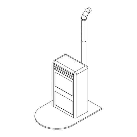
Page 14: Identification Of The Q9 Ducted Insert Components
IdentIfIcatIon of the Q9 dUcted Insert components The Q9 DUCTED stove/insert is made up from the parts indicated in Figure 1 Figure 1 Parts that make up the stove/insert - mod. Q9 DUCTED parts LIst eLement QUantIty descrIptIon Ducted air conveyor box... - Page 15 The protective frame unit is supplied with the insert, but disassembled from the same, therefore the insert must be assembled in the installation phase, after the frame has been pre-assembled (see Figure 2). Figure 2 Parts that make up the protective frame - mod. Q9 DUCTED parts LIst...
-
Page 16: General Warnings For Q9 Installation
GeneraL warnInGs for Q9 InstaLLatIon Š The stove/insert must be installed on a levelled surface that can support its weight. Š The minimum space to be left with respect to the rear walls is 10-15 cm. Š Only use stainless or glazed steel pipes with leak-tight gasket. No flexible hoses of any type are allowed. - Page 17 Q9 insert clearance Open Q9 insert clearance ENGLISH...
-
Page 18: Measurements Necessary For Correct Installation
measUrements necessary for correct InstaLLatIon Lower part of the chimney vent: minimum opening 500 cm²; Upper part of the chimney vent: minimum opening 550 cm². In front view, 5 cm of free volume must be guaranteed on the 3 LH, RH and upper sides. For aesthetic reasons, these areas are masked via: Š... -
Page 19: Q9 Ducted Installation
Q9 dUcted InstaLLatIon The insert is provided on an iron sliding base, which allows it to be installed in a pre-existing chimney. This sliding base allows to extract the insert easily both for loading the pellets inside the tank and for any maintenance or end of season cleaning. -
Page 20: Assembly With Sliding Base
assemBLy wIth sLIdInG Base Take the sliding base and position it in the existing chimney. Using a piece of chalk or pen, mark the base blocking holes on the surface of the chimney. Make holes for the 8 mm steel expansion plugs. Make a 60 mm hole in correspondence with the air vent. - Page 21 Figure 4 When the insert has been inserted completely, turn the flap with the relevant wrench anti-clockwise in order to fix it and restore it with the electric energy. Proceed as follows to release and slide the insert out on the tracks, in the event of maintenance or pellet loading: 1.
-
Page 22: Positioning The Appliance In A Pre-Existing Chimney
posItIonInG the appLIance In a pre-exIstInG chImney 1=Internal air inlet (environment air vent, min. 500cm2) 2= Internal air outlet (min. 500cm2) A= Pre-existing chimney hood opening for passage of hot air into the covering counter-hood F=Incubated flue (min. ø 10cm, max. ø15cm) T=Protective closure plate of the fitting to the flue Before installation, it is necessary to thoroughly clean the chimney (fire surface base and flue) where the appliance is to be inserted;... -
Page 23: Assembly Procedure With Pedestal
(optIonaL) Description of components: Š Q9 DUCTED Š Height-adjustable pedestal Š Lateral loading hopper Š Adjustable hopper support assemBLy procedUre wIth pedestaL Position the base in the desired point and adjust to the desired height through the feet (the bolts are positioned in the four external sides of the pedestal at the bottom). - Page 24 Finally, open the fire door and turn the screw positioned in the bottom left-hand corner clockwise, using the spanner provided. To understand whether the insert is correctly attached to the base, connect the plug to the current socket and check that the display switches on.
- Page 25 Insert on existing chimney: installation area requirements parts LIst eLement descrIptIon Internal air inlet Internal air outlet Smoke exhaust Pipes Smoke exhaust pipes The figure below indicates an electric component present on the left side of the stove/insert: Š Safety thermostat (manual reset), which starts to run if the smoke fan or exchanger should block (see Figure below on the right).
-
Page 26: Positioning Appliance On The Support Pedestal
posItIonInG appLIance on the sUpport pedestaL 1= Internal air inlet (environment air vent, min. 500cm2) 2= Internal air outlet (min. 500cm2) I= Rock wool insulation - thickness 4cm - density 80kg/m3 F= Incubated flue (min. ø 10cm, max. ø15cm) L= Finishing pilaster or counter-hood in fire-proof plasterboard sustained by a framework of galvanised supports. -
Page 27: Ducting
All Adjustment, insPection And cleAning Activities must be Performed by quAlified stAff. In the Q9 DUCTED stove/insert, there is the dual possibility to use an air flow on the back of the stove that can be ducted and transported to another room. -
Page 28: Pellets And Feeding
Š en Plus - uni en 16961 - 2 class a1 or a2 Š Ö-norm m 7135 Š din Plus 51731 Opera recommends using pellets with a diameter of 6mm with its products. Pellet storage To guarantee combustion without problems, the pellets must be kept in a dry place. -
Page 29: Q9 Ducted Technical Data
The table below gives the appliance technical data. Q9 DUCTED TECHNICAL DATA Thermal output Nominal Thermal output Thermal output 3.50 Reduced Thermal output 87.5 Nominal Yield Thermal output 89.0 Reduced Thermal output Nominal Exhaust gas temperature °C Thermal output Reduced Thermal output 8.18... -
Page 30: Operator Interface
OpErATOr INTErfACE Hand-held remote control The hand-held remote control is made up from the following components provided in the Q9 inserts (optional in the stoves): – Hand-held remote control – TX/RX receiver module – Re-charge base Hand-held terminal The hand-held radio terminal completely replaced the display console... -
Page 31: Configuration With The Appliance
ON. Activation is confirmed by an acoustic signal. 3. Press any button on the radio command repeatedly until "Opera" appears on the display (if configured with a stove, the same wording of the appliance command panel will appear). whenever the appliance is not configured, "No signal"... -
Page 32: List Of Quick Commands
LIsT Of QUICk COmmANDs display contrast control From the main screen, operate on keys P5 and P6 to increase and decrease respectively. back-lighting level control While holding key P3 down, simultaneously operate on keys P5 and P6 to increase and decrease respectively. Keyboard lock (children's safety) activation and deactivation: Press keys P5 and P6 simultaneously and then key P1. - Page 33 There are 20 appliance operating powers managed automatically by the appliance on the basis of room temperature and the temperature set, in [MaNuaL] mode and in [CHRONO] mode. MiéRCOLEs (WEDNEsDaY) 31/07/2013 WEDNEsDaY 31/07/2013 WEDNEsDaY 31/07/2013 MaNuaL (MaNuaL) MaNuaL MaNuaL ATTENTION if the difference between the current room temperature and the desired temperature is below 5°C, the appliance will not go to maximum power (20) but will use the 11th power level as the upper limit.
-
Page 34: Manual Mode
mANUAL mODE To modify the temperature set in MaNuaL mode, operate on the main screen; press the key once at any time and then the [+] and [-] to increase or decrease it. The room temperature is indicated at the top of the display and the temperature set at the bottom. - Page 35 in CHRONO mode it is possible to set 3 different working temperatures: COMFORT, NORMaL and ECONOMY Š COMFORT sETTiNg submenu Š NORMaL sETTiNg submenu Š ECONOMY sETTiNg submenu COMFORT sETTiNg COMFORT sETTiNg NORMaL sETTiNg NORMaL sETTiNg ECONOMY sETTiNg ECONOMY sETTiNg TEMPERTuRE TEMPERTuRE TEMPERTuRE...
-
Page 36: Switching The Appliance Off
in the example given in the figure at the end of the page: Š at 06.30 the stove/insert is activated at level 3 (comfort) Š at 12.00 the stove/insert switches off and remains off until 17.30 Š at 17.30 the stove/insert is activated at level 1 (economy) Š... -
Page 37: System Status
fuel starts to fall into the burner. The display shows the auger activation time in seconds. To exit and go back to the screen relative to the user menu, press the button. PRELOaDiNg PRELOaDiNg PREss + kEY PREss + kEY LOaDiNg LOaDiNg Š... -
Page 38: General Settings
LOAD sETTINg LOAD sETTINg NO CORRECTiON NO CORRECTiON To increase or decrease the parameter set, operate on the [+] and [-] buttons respectively. The percentage correction relative to each set is also displayed in the lower part of the screen. VENTILATION sETTINg setting not necessary gENErAL sETTINgs... -
Page 39: Stand-By
To activate [ON] and deactivate [OFF] press the [+] and [-] buttons respectively. To exit and go back to the previous screen press button. sTAND-by allows the activation and deactivation of the sTaND-BY operation status. By deactivating the sTaND- BY operating status, the appliance does not switch off by exceeding the set room temperature by 2°C, but remains on in the ECO operating status. -
Page 40: Logs
LOgs allows to display the recordings of the alarm signals occurring. Each recording is preceded by the date and time of the alarm; the system memory allows to record up to 30 events. 1205061642 1205061642 safety al. safety al. The alarm signal stated above indicates that in 2012 (12) in the month of May (05) day 6 (06) at 16:42 (1642) the "safety al." occurred. -
Page 41: Alarms
ALArms The following alarms are envisioned, whose activation takes place with a delay of 60" after the corresponding event has occurred. On expiry of this time without the event having returned, the stove/insert passes to the alarm status with immediate shutdown of the stove/insert and activation of the smoke fan and the exchanger fan at maximum speed. -
Page 42: Hand-Held Terminal Breakage
HAND-HELD TErmINAL brEAkAgE if the radio control breaks, OPERa has installed an additional switch on the Q9 insert to fire and/or shutdown the appliance in the case of breakage or faults in the hand-held terminal. This switch is used exclusively in exceptional cases such as malfunctioning/breakage of the hand-held terminal. if the appliance is on and the radio command cannot be used, by activating the red safety switch with a pointed object (e.g. -
Page 43: Appendix "A" Automatic Mode
AppENDIX "A" AUTOmATIC mODE The automatic power management systems have the following peculiarities: Š no power sETTiNg menu (also in chrono settings) Š 20 power levels automatically determined depending on the difference between the room temperature and the user temperature sETTiNg. Š... -
Page 44: Maintenance
mAINTENANCE NOTEs ON mAINTENANCE inspection and maintenance activities must be performed by specialized technicians who are familiar with the instructions in this manual. Before performing any type of operation, make sure that: Š the power cable is unplugged since the stove could be programmed to start. Š... - Page 45 CLEANINg THE COmbUsTION CHAmbEr ATTENTION mAkE sUrE THE sTOVE Is COLD! NOTE Clean the fire pot and other parts of the combustion chamber every 2/3 days if using good quality, name brand pellets and daily if using low quality pellets. Use a vacuum cleaner with an ash container.
- Page 46 pErIODIC CLEANINg Š use the suction device inside the fire pot (see figure at the side a) when required (when the fire pot is loaded). Š suck the areas to the left and right where the fire pot is housed (see figure at side B) when required (when the fire pot is loaded).
-
Page 47: Suggestions For Proper Use
1) if used or installed improperly, the pellet stove could cause damage and maximum efficiency is not ensured. 2) OPERa provides the user with all information regarding safe use of the stove in order to avoid injury or damage to property or parts of the stove. - Page 48 ENGLISH...
- Page 49 ENGLISH...
- Page 50 ENGLISH...
- Page 51 ENGLISH...
- Page 52 Tel. 0445/300810 - Fax 0445/300372 - opera.info@dalzotto.com - www.operastyle.it Opera is a trademark of Dal Zotto, which reserves the right to make changes to thefeatures and data contained in this document at anytime and without prior notice, in order to improve its products.
Need help?
Do you have a question about the Q9 and is the answer not in the manual?
Questions and answers