Advertisement
Programmable Shift Controller
WARNING: During installation, disconnect the battery cables. When disconnecting, always
remove the Negative cable first and install it last.
Parts Included:
1 – Shift Controller
1 – Pro-Data+ Software
1 – 9-Pin Harness, 10-Feet
2 – Deutsch Terminated Harnesses
Note: Solid core spark plug wires cannot be used with this controller.
The MSD Programmable Shift Controller allows you to
program different rpm points to trigger the shift solenoids.
Any transmission configuration may be used up to a six
speed trans. Programming the rpm and options of the Shift
Controller can be done with MSD's Hand Held Monitor, PN
7550, or with the MSD Pro-Data+ Software on a Windows
based PC.
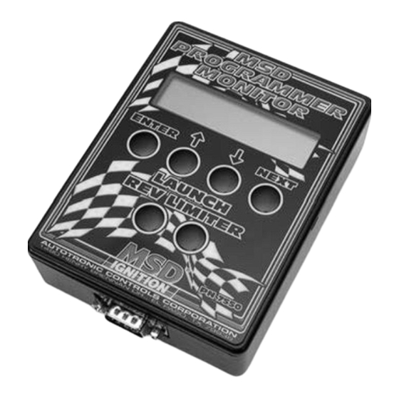
The optional Hand Held Programmer/Monitor, PN 7550,
connects through the 9-pin connector on the Control and
features an LCD display that allows you to walk through the
programs as well as monitor the engine's rpm, the current
gear, alerts and more (Figure 1).
There is also a computer disk supplied with the MSD
ProData+ software. This software is for PCs running windows
95, 98 or NT. All of the adjustable parameters can be reviewed
and set, then uploaded to the Controller. More information
on using this software begins on page 5.
MSD
PN 75591
8 – #10 Screws
4 – #10 Nuts
4 – #10 Washers
1 – 1-Pin Harness
10 – Butt Splices
2 – Ring Terminals
Figure 1 Hand Held Programmer, PN 7550.
Advertisement
Table of Contents

Related Manuals for MSD 75591


Summary of Contents for MSD 75591
- Page 1 Any transmission configuration may be used up to a six speed trans. Programming the rpm and options of the Shift Controller can be done with MSD’s Hand Held Monitor, PN 7550, or with the MSD Pro-Data+ Software on a Windows based PC.
- Page 2 Note: To test the Dark Blue wire's operation, the engine must be running so the Shift Controller receives a trigger signal. MSD offers an optional tester, PN 8998, that allows you to test the Controller without the engine running. See page 6.
- Page 3 INSTALLATION INSTRUCTIONS LEDS There are six LEDs on the end panel of the Controller. The Red status LED will be on steady when the unit is turned On. Once the launch reset wire is activated (Dark Blue) this LED will blink rapidly (this is handy during clutch setup).
- Page 4 SWITCH 12 Volts Note: NHRA's rules only allow one wire to be connected to the Trans Brake. Connect the MSD Dark Blue (reset) to the Trans Brake Switch. The Two or Three Step Activation wire can connect to the Pink wire of PN 75591.
- Page 5 Saved/Transferred to the MSD Controller. The software gives you the choice of automatically transferring the change to the MSD or the PC. Save to MSD: By saving the change right to the MSD, the new change is automatically put into the Controller.
- Page 6 INSTALLATION INSTRUCTIONS MSD LED SHIFT LIGHT PN 7552 /GREEN ORANGE/YELLOW Hand Held Programmer PN 7550 or Laptop with MSD Pro-Data+ Software Shift Solenoids MODULE SELECTOR PN 8739 AUTOTRONIC CONTROLS CORPORATION 1490 HENRY BRENNAN DR, EL PASO, TX 79936 PINK MODULE 2...
Need help?
Do you have a question about the 75591 and is the answer not in the manual?
Questions and answers