
Related Manuals for 3onedata CAN485


Summary of Contents for 3onedata CAN485
- Page 1 Shenzhen 3onedata Technology Co., Ltd CAN485 Interface Converter User Manual Version 1.0.0, Feb 2016 Shenzhen 3onedata Technology Co., Ltd www.3onedata.com...
- Page 2 Shenzhen 3onedata Technology Co., Ltd Statement Copyright Notice Information in this document is reserved by Shenzhen 3onedata Technology Co., Ltd. Reproduction and extract without permission is prohibited. Trademarks Notice is registered trademarks of Shenzhen 3onedata Technology Co.,Ltd. All other trademarks or regitered marks in this manual belong to their respective manufacturers.
-
Page 3: Table Of Contents
Shenzhen 3onedata Technology Co., Ltd Content Chapter 1 Summarize ................................1 1.1 Introduction ................................1 1.2 Product Features ................................. 1 1.3 Specification ................................2 Chapter 2 Hardware Description ............................3 2.1 Interface Description ..............................3 2.2 Interface Description ..............................4 2.2.1 Power Input ................................. -
Page 4: Chapter 1 Summarize
Chapter 1 Summarize 1.1 Introduction CAN485 is used for data exchange between CAN-Bus field bus and RS-485 bus interface converter, and supports Modbus RTU protocol. CAN485 interface converter integrated a RS-485 channel and a CAN-Bus channel can be easily embedded using RS-485 interface for communication nodes, do not need to change the original hardware architecture enables the device to obtain the CAN-Bus communication interface, to achieve between the equipments of RS-485 and CAN-Bus network connection and data communication. -
Page 5: Specification
Shenzhen 3onedata Technology Co., Ltd 1.3 Specification Serial Interface Standard: RS-485 RS-485 signal: D-, D+, GND Parity bit: None, Even, Odd, Space, Mark Data bit: 8bit Stop bit: 1bit, 2bit Band rate: 300bps~115200bps Transfer distance: no more than 1200m Connector: DB9 Male CAN-Bus Interface Standard: CAN2.0A, CAN2.0B... -
Page 6: Chapter 2 Hardware Description
Shenzhen 3onedata Technology Co., Ltd Chapter 2 Hardware Description 2.1 Interface Description Top view Front and Rear view Side view www.3onedata.com... -
Page 7: Interface Description
2.2.1 Power Input CAN485 interface converter provide DC power input, voltage input is the two terminal form, plug type 2 core spacing of 5.08mm terminals, wherein the power input range of 9 ~ 48VDC. The power support is not polarity that the device can still work normally after the reverse. -
Page 8: Led Indicator
RES+ and RES- to achieve terminal resistor accession, as shown below. When the CAN485 converter is used as the CAN-Bus network terminal, the two pin is connected to a resistance of 120Ω, otherwise no need to install a 120Ω resistor. -
Page 9: Dip Switch
Shenzhen 3onedata Technology Co., Ltd 2.4 DIP Switch The converter front panel provide 4 bit DIP switch to set function (ON is effective). 1 and 4 keep for future function. 2 is for configuration mode settings. 3 is recovery default factory. Please power off and power on when you change the status of DIP switch. - Page 10 Shenzhen 3onedata Technology Co., Ltd Pigtail cannot be tied and swerved as less as possible. Swerving radius cannot be too small (small swerving causes terrible loss of link). Its banding should be moderate, not too tight, and should be separated from other cables.
-
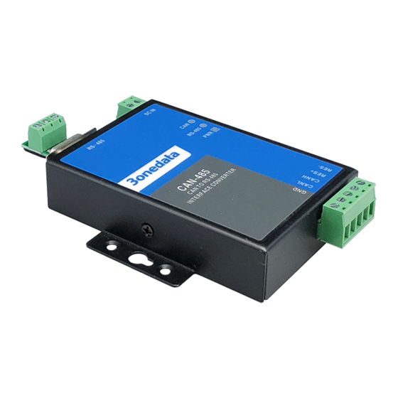
Page 11: Chapter 3 Appearance And Dimension
Shenzhen 3onedata Technology Co., Ltd Chapter 3 Appearance and Dimension Appearance: CAN485 Dimension (Unit: mm) www.3onedata.com... -
Page 12: Chapter 4 Packing List
Shenzhen 3onedata Technology Co., Ltd Chapter 4 Packing List The first time use this product, please check the packaging is intact or not and the attachment is complete or not at first. Item Quality Interface Converter 1pcs User manual 1pcs... -
Page 13: Chapter 5 Overview Of Product Configuration
(Figure 5.2) CAN485 converter configuration software is included in the CD products. The interface of the software is shown in figure 5.2. Set the software to memory and display parameters of the CAN485 converter the last successful set (if it www.3onedata.com... -
Page 14: Conversion Parameter
Shenzhen 3onedata Technology Co., Ltd fails, parameter settings will not be saved), avoid the user forgetting your own configuration. The product can be used to dial the code switch to restore factory settings set. In the converter enter configuration mode, to set the parameters in the software or software that is not connected to the converter. - Page 15 Shenzhen 3onedata Technology Co., Ltd The position of the CAN-Bus frame ID in the serial frame: The function only effective in the transparent tape identification parameter conversion mode. Convert the CAN-Bus message in the serial data, start byte frame ID CAN-Bus message in the serial frame offset address ID and frame length (see 6.2 transparent with mark conversion).
-
Page 16: Com Parameter
Shenzhen 3onedata Technology Co., Ltd 5.2.2 COM parameter (Figure 5.2.2) Baud rate: 300bps~115200bps Serial parity: none, even and odd, marks, spaces and stop these 6 options. No matter what kind of check mode converter, serial transmission of data bits is 8. No parity only add 1 start bit and 1 stop bit (10 bit), the other four modes plus 1 parity bits or stop bit (total of 11). -
Page 17: Keys Description
Shenzhen 3onedata Technology Co., Ltd Baud rate: baud rate of CAN-Bus standard, the baud rate is CIA recommended list. Frame type: in frame type conversion of the CAN-Bus message, a standard frame and extended frame optional, does not support remote frame. -
Page 18: Chapter 6 Application Description
Shenzhen 3onedata Technology Co., Ltd Chapter 6 Application Description 6.1 Transparent conversion Transparent conversion mode converter receives side bus data immediately sent to the other side of the bus conversion. So based on data stream way, maximally improve the speed of the converter, but also improve the buffer utilization, because in the reception at the same time converter also in converting and transmitting and vacated the receive buffer. -
Page 19: Conversion Example
Shenzhen 3onedata Technology Co., Ltd 2. CAN-Bus message to serial frame Received CAN-Bus message one frame immediately forwarded a frame. The conversion of the CAN-Bus packets in the Data Field data are converted to serial frames. If in the configuration of the time frame information conversion enabled option "conversion", so the converter will frame bytes of information CAN-Bus message directly to the serial frame filling. -
Page 20: Transparent With The Identity Conversion
Shenzhen 3onedata Technology Co., Ltd 2. CAN-Bus message to serial frame The configuration for frame information conversion of the CAN-Bus message, but the ID frame is not converted. Serial frame CAN message (standard frame) Frame information Frame ID 1 Frame ID 2 Data Field 6.2 Transparent with the identity conversion... -
Page 21: Conversion Mode
Shenzhen 3onedata Technology Co., Ltd CAN-Bus frame: The CAN-Bus message format unchanged, only the corresponding ID of the CAN-Bus frame will be converted to serial frames. 6.2.2 Conversion mode 1. Serial frames conversion CAN-Bus message CAN-Bus with serial frame identification in serial frame start address and length can be set by the configuration. 0 ~ 7 is the starting address and length are respectively 1~ 2 (standard frame) or 1 ~ 4 (extended frame). -
Page 22: Conversion Example
Shenzhen 3onedata Technology Co., Ltd CAN message (standard frame) Serial frame Frame information Frame information Data 1 Frame ID 1 Frame ID Data 2 Frame ID 2 Data 3 Data 1 Frame ID 1 Data 2 Data 4 Data 3... -
Page 23: Modbus Rtu Conversion
Shenzhen 3onedata Technology Co., Ltd 2. CAN-Bus message to serial frame Assume that CAN-Bus identifies the starting address in the serial frame is 2, the length is 3 (extended frame case), CAN-Bus message and converted into serial frames results are shown as follows. - Page 24 Shenzhen 3onedata Technology Co., Ltd Make reference to the segment transfer protocol message segment in DeviceNet. Segmented message format are shown in (to extend the frame as an example, standard frame is just a different length of the frame ID, other the same format), transmission of Modbus protocol can from "data 2"...
-
Page 25: Conversion Mode
Shenzhen 3onedata Technology Co., Ltd 6.3.2 Conversion mode The process of conversion in the lateral side of the serial CAN-Bus converter, will only receive a complete and correct Modbus RTU frame will be converted, otherwise no action. As shown below, the address domain Modbus RTU protocol into CAN message frame ID ID4 (extended frame) ID2 (standard frame), marks the same in the conversion process. -
Page 26: Attention Matters
Using CAN485 converter, should pay attention to both sides of the bus baud rate and data transmission time interval rationality, conversion should consider the affordability of the low baud rate of bus data. For example, when CAN-BUS were converted to serial bus, CAN-BUS can reach the rate of thousands of frames per second, but the serial bus only to the hundreds of frames per second. -
Page 27: Chapter 7 Repair And Service
Shenzhen 3onedata Technology Co., Ltd Chapter 7 Repair and Service The company provides a three-year product warranty, from the date of shipment. According to the product specifications, during the warranty period, the company will be free to repair or replace the product if the product has any failure or operation fails.
Need help?
Do you have a question about the CAN485 and is the answer not in the manual?
Questions and answers