Table of Contents
Advertisement
WIRING AND COMMISSIONING INFORMATION FOR
SATCHWELL MICRONET MN650
CONTROLLERS
APPLICATION
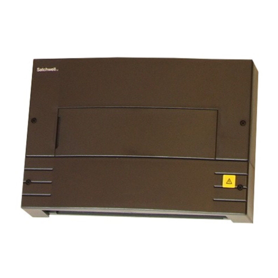
Satchwell MicroNet MN650 Series Controllers are fully-programmable
controllers designed for roof top, unit ventilator, air handling unit (AHU)
and zone heating and cooling applications. These controllers feature
universal inputs (UIs), digital inputs (DIs), triac outputs for 24Vac loads,
analogue outputs (AOs) and support for one MN-Sx digital sensor. The
MN650 controller operates from an external 24Vac or 24Vdc supply.
By setting the controller's jumper pins, any of the universal inputs may
be configured as an analogue, resistive, or dry (volt free) contact input.
MN650 controllers can operate standalone or be networked in a
®
MicroNet ARCNET
network or a Native Communications Protocol
(NCP) network. For any model of controller, a PC with VisiSat™
Configuration Tool software is necessary to download and modify
applications.
SPECIFICATION
Order Type
MN650-ARC
MicroNet 650 ARCNET
Controller
MN650-NCP
MicroNet 650 NCP Controller
MN650-XCOM
MicroNet 650 Dual NCP
Controller
Data Sheets
DS 10.154 - MN650 Controllers
DS 10.202 - VisiSat Configuration Tool
Multi-Lingual Instructions
MLI 10.154 - Installation Instructions
MLI 10.310 - MN DK Installation Instructions
Description
Communications
ARCNET
Dual NCP
An optional Real-Time Clock card can be fitted, which maintains
controller time during a power failure. The RTC card contains a 3V,
125mAh Lithium cell which has a life of at least 5 years.
Networked controllers receive time updates automatically from a
MicroNet Manager Interface or Touch Screen time master.
A Satchwell MicroNet Touch Screen or LCD can be mounted onto the
controller, which allows a user to view and modify controller properties.
Please refer to the Touch Screen Engineering Data Sheet (DS
10.050A) or to the LCD Engineering Data Sheet (DS 10.060A).
The controller also features an onboard power capacitor, to preserve
RAM for a maximum of seven days.
Voltage
24Vac
12 Universal inputs configurable for temperature, digital
50/60Hz
input or voltage (0 to 10Vdc) input.
or
4 AOs providing 0 to 10Vdc at 1mA. Load resistance must
NCP
24Vdc
be 10kΩ or more.
8 DIs - Volt Free Contact (VFC) or wet contact (24Vac or
24Vdc).
8 Triac outputs for 24Vac.
15Vdc (25mA) supply output for humidity and pressure
sensors, etc.
1 S-Link sensor.
MN650
Inputs/Outputs
Satchwell
Advertisement
Table of Contents

Related Manuals for Satchwell MN650 Series

Summary of Contents for Satchwell MN650 Series
- Page 1 MicroNet Manager Interface or Touch Screen time master. MN650 controller operates from an external 24Vac or 24Vdc supply. A Satchwell MicroNet Touch Screen or LCD can be mounted onto the By setting the controller’s jumper pins, any of the universal inputs may controller, which allows a user to view and modify controller properties.
-
Page 2: Installation
INSTALLATION Federal Communications Commission (FCC) This equipment has been tested and found to comply with the limits for Inspection a Class A digital device, pursuant to Part 15 of the FCC Rules. These limits are designed to provide reasonable protection against harmful Inspect carton for damage. - Page 3 Mounting Location Panel or DIN Rail Mounting The controllers are suitable for indoor use only. When selecting a mounting location, make certain the following conditions are met: 1. Select mounting location. Allow minimum 150mm clearance • Do not install where excessive moisture, corrosive fumes, vibration, around controller.
-
Page 4: Terminal Connections
Terminal Connections Terminals accept one 1.5mm wire Terminals 1 to 17 are internally linked. 1 2 3 4 5 6 7 8 9 10 11 12 13 14 15 16 17 18 19 20 21 22 23 24 25 26 27 28 29 30 31 32 33 34 35 36 37 38 39 40 41 42 43 44 45 46 47 48 49 50 51 52 53 54 55 56... - Page 5 ARCNET Network Wiring Controllers may be networked to either a 'main LAN' under an MN50-MI-ARC or to a 'sub-LAN' under an ARCNET router (MN50-MI-RTR). For performance reasons, when transferring network variables between controllers and Touch Screens, the main LAN should have only ARCNET routers connected to it, unless there are no sub-LANs.
- Page 6 S-Link Sensor Wiring 4. Make certain jumper is in Voltage position. 1. Review the Precautions section. Configure input as Voltage UI 2. Connect unscreened cable to terminals . Polarity makes 18, 19, 20, 21, 22, 23, 24, 25, 26, 27, 28 no difference.
-
Page 7: Power Supply Wiring
Digital Input (DI) Wiring Power Supply Wiring The digital inputs may be used as simple equipment status inputs. Notes: 1. Review the Precautions section. 1. If using a touch screen via the ribbon cable, the MN650 must be supplied from 24Vac, not 24Vdc. 2. - Page 8 CHECKOUT Cold and Warm Starting the Controller Electrical Checkout Cold Start Caution: If the controller’s Configuration Locked property has not 1. If controller is part of a MicroNet NCP or ARCNET network, verify been set to Yes in VisiSat, the cold start procedure clears all network wiring between controller and other devices is installed configuration data from the non-volatile EEPROM of the according to job wiring diagram and national and local electrical...
-
Page 9: Controller Status Leds
CONTROLLER STATUS LEDs SERVICING The Controller Status LEDs LD3 and LD5 have the following meanings: Components within the controllers cannot be field repaired. If there is a problem with a controller, carry out the following procedure before LD3 (Red, ’Error’ LED) Indicates that the unit has a problem requiring contacting your local sales office. -
Page 10: Dimension Drawing
• The design and performance of TAC Satchwell equipment is subject to improvement and therefore liable to alteration without notice. • Information is given for guidance only and TAC Satchwell does not accept responsibility for the selection or installation of its products unless information is given by the Company in writing relating to a specific application.