
Related Manuals for IRO 1131 CAN plus


Summary of Contents for IRO 1131 CAN plus
- Page 1 Ref. No. 31-8931-0201-06/0536 IRO AB Box 54 SE-523 22 Ulricehamn Sweden 1131 CAN plus Tel (Int+46) 321 29700 Fax (Int+46) 321 29800 www.iroab.com info@iro.se Operating Instructions English...
-
Page 2: Table Of Contents
System orientation ........................Settings ............................N/R rotation - Yarn separation ..................... Balloon control/ Threading......................Rotating the spool body....................... 10 Maintenance..........................11 Fault finding..........................12-13 IRO AB RESERVE THE RIGHT TO CHANGE THE CONTENTS OF THE USER’S GUIDE AND TECHNICAL SPECIFICATIONS WITHOUT PRIOR NOTIFICATION. -
Page 3: Technical Specifications
ZONES CLASSIFIED ACCORDING TO THE EUROPEAN DIRECTIVE 94/9/EC. PLEASE CONTACT IRO AB IF PRODUCTS FOR USE IN A POTENTIALLY EXPLOSIVE ATMOSPHERE ARE REQUIRED. TO COMPLY WITH CE. REGULATIONS ONLY REPLACEMENT PARTS APPROVED BY IRO AB MAY BE USED. Technical specifikations... -
Page 4: Installation/ Mains Connection
1131 CAN plus Installation/ Mains Connection Installation NOTE Condensation can form on the weft feeder when it is moved from the cold environment of the warehouse to the warmer environment of the loom room. Make sure that the feeder is dry before switching it on. -
Page 5: Operating Diagram
1131 CAN plus Operating Diagram Operating diagram Motor Accessories Motor control unit Interface extension (12 colour) Extension Interface Signal... -
Page 6: Main Parts
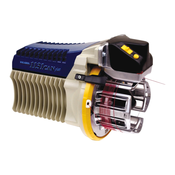
1131 CAN plus Main Parts Side view Stopper unit Magnet finger Pneumatic threading (PTU) Fixed finger Yarn transport finger Winding disc Front view On/Off switch Magnet release button Signal lamp Winding sensor/ Yarn store sensor... -
Page 7: System Orientation
1131 CAN plus System Orientation System orientation SYSTEM The system consists of feeders, cables to each feeder, interface control box, PTU (pneumatic threading up), input yarn tensioners and external accessories such as bobbin break sensors and bobbin change detectors. INTERFACE This control box handles all communication between feeders and machine via the CAN-bus system. -
Page 8: Settings
1131 CAN plus Settings Spool body circumference The required pick length is the deciding factor when calculating the spool body circumference and the number of windings for each pick. The table below indicates the pick length ranges that can be obtained from different numbers of windings. -
Page 9: N/R Rotation - Yarn Separation
1131 CAN plus N/R Rotation and Yarn Seperation Adjustment Adjusting N/R rotation and yarn separation This adjustment is carried out by locking the inclined hub in position and then revolving the winding disc in a clockwise or anti-clockwise direction. Proceed as follows: Insert a three millimeter socket key (or similar object) into the hole (A) in the cone at the front of the spool body. -
Page 10: Balloon Control/ Threading
1131 CAN plus Balloon Control/ Threading Balloon control To ensure optimal yarn performance between the feeder and the weaving machine it may be beneficial, especially when weaving heavier yarns, to use a cone for balloon control. During the initial installation the cone should be... -
Page 11: Rotating The Spool Body
1131 CAN plus Rotating the spool body Rotating the spool body Balloon control WARNING!! Failure to follow these instructions will result in damage to the spool body, stopper magnet, stopper magnet pin or the stopper housing With feeder connected to the weaving machine and machine power on. -
Page 12: Maintenance
1131 CAN plus Maintenace Maintenance It is recommended to carry out a periodical cleaning of any lint or dust accumulation on the feeder or the control box. min 20 cm The unit requires no extra lubrication. IMPORTANT! The connector cover must be assembled. -
Page 13: Fault Finding
1131 CAN plus Fault finding Voltage check +24V DC PGND +290V DC Interface check Fuse T5A/ 250 V 24V DC for feeder Code switch settings and communication feeder size CAN enabled Fuse T3,15A/ 500V 290V DC, feeder motor Fuse T0,75A/ 250V 24V DC. - Page 14 10-21-23-24 Loom terminal indicates “Blocked rotor”. Communication failure beween loom and feeder. 2-3-24-25 Feeder 1131 CAN Plus is displayed as 2231 CAN Plus at loom terminal. 8-23-24 Frequent problems with long or short picks. 11-28-23-24 Feeder indicates bobbin break but the yarn is not broken.
Need help?
Do you have a question about the 1131 CAN plus and is the answer not in the manual?
Questions and answers