
Related Manuals for RFS 48810A

Summary of Contents for RFS 48810A
- Page 1 48810A & 48810B User's Manual • • 200 Pondview Drive, Meriden, CT 06450 (877) 737-9675 Fax (203) 821-3852 www.rfsworld.com...
- Page 2 Disclaimer All information and statements contained herein are accurate to the best of the knowledge of Radio Frequency Systems, but Radio Frequency Systems does not make any warranty with respect thereto, including without limitation any results, which may be obtained from the products described herein or the infringement by such products of any proprietary rights of any persons.
-
Page 3: Table Of Contents
Table of Contents General Statements Maximum Permissible Exposure Limits Product Overview Field Tune-up, Alignment or Calibration FCC ID and Canada Certification Numbers Theory of Operation Electrical Specifications Mechanical Specifications Environmental Specifications Intermodulation, Power, and AGC AGC Automatic Shutdown Manual Gain Adjustment AC/DC Power Grounding and Surge Protection Antenna Isolation... -
Page 4: General Statements
General Statements Thank you for selecting this RFS product. We are confident that you will find this product in proper working order, meeting all stated specifications. If not, please contact customer service immediately at 1-800-321-4700 and we will resolve the issue without hesitation. -
Page 5: Maximum Permissible Exposure Limits
Maximum Permissible Exposure Limits THIS PRODUCT IS CATEGORICALLY EXCLUDED FROM ROUTINE ENVIRONMENTAL EVALUATION ACCORDING TO CFR 47, SECTION 1.1037 AND 2.1091. Repeaters like the 48810 generate radio signals and thereby give rise to electromagnetic fields. The installer is expected to have a complete understanding of CFR Title 47, Sections 1.1307, 1.1310 and 2.1091. -
Page 6: Product Overview
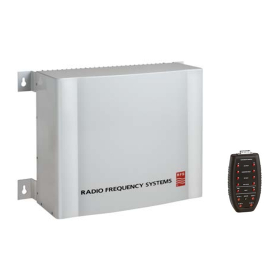
The 48810A and 48810B repeaters are designed to enhance radio communication in buildings, basements, tunnels and other RF shielded environments. The 48810A has a 15 MHz band customer selectable to A,B, or C block, the 48810B has a 5 MHz band selectable to D, E, or F block. -
Page 7: Electrical Specifications
Electrical Specifications Downlink Uplink 48810A, Block, selectable A, B, C A, B, C 48881B, Block, selectable D, E, F D, E, F Gain, no attenuation 87 dB 87 dB Gain Flatness, typical ±1.0 dB ±1.0 dB Manual Attenuator Range 20 dB... -
Page 8: Agc Automatic Shutdown
In typical operation, the AGC is only active when needed to prevent overdrive. If the AGC is constantly activating, RFS suggests that you reduce the gain via the manual attenuator and verify that an oscillation between the base and service antenna systems does not exist. -
Page 9: Ac/Dc Power
Other factors influencing isolation include multi-path reflections, structures, other antennas, passing vehicles, personnel proximity, etc. Contact RFS Applications Engineering for further assistance. It is always best to measure the isolation before connecting the repeater. The most direct way to measure the isolation is to inject a known signal into one antenna, and measure the coupled signal at the other antenna. -
Page 10: Installation
Generally, it is desired to minimize the amount of coax that has to be installed. However, in buildings with extensive obstructions, it may be necessary to install several service area antennas. For assistance with antenna placement, contact RFS Applications Engineering. IMPORTANT... -
Page 11: Diagnostics/Troubleshooting
Mount repeater upright, with the connections toward the floor. Ensure there is sufficient space above and below the unit to allow airflow through the heat sink. Check to make sure the AC power cord can reach the power source. Also, provide adequate bending radii for the coaxial cables. -
Page 12: Test Points
PM800. A 30-foot extension cable (part #: 103300014900) is also available for remote mounting or the PM800 can be directly plugged into the 15-pin test port located on the front plate of the repeater. Should the performance monitor become damaged, contact RFS customer service at 1-800-321-4700 to order a replacement. - Page 13 Pin 9: Max sink = 8 mA. Max input = 6.0 VDC Pin 9 is a remote disable feature. Connecting pin 15 to pin 9 via a relay will cause the repeater to shut down. This can be accomplished with a remote control unit like the RFS RPM700 (remote performance monitor).
-
Page 14: Component Location
Pin 15 can be used as the drive voltage to disable the unit using Pin 9. It is also used to power the PM800-10 performance monitor, when attached. Component Location 48810 Field repair for the 48810 is recommended only for the following parts: 48810A 48810B Downlink Uplink Downlink... -
Page 15: Maintenance, Repair And Warranty
Maintenance, Repair and Warranty Periodic Maintenance There is no periodic maintenance required for the 48710 or 48722. As long as the repeaters are kept away from extreme temperatures and moisture, they should provide long-term, carefree operation. However, as a system, periodically check all RF connections for corrosion, strain damage, and proper tightness.
Need help?
Do you have a question about the 48810A and is the answer not in the manual?
Questions and answers