
Related Manuals for Marine Instruments M3P-T

Summary of Contents for Marine Instruments M3P-T
- Page 1 M3P / M3P-T BUOYS. User’s Manual V1 M3P/M3P-T/M3P-R BUOYS LONGLINE UM022EN USER MANUAL...
-
Page 2: Table Of Contents
UM022EN M3P / M3P-T / M3P-R BUOYS. User Manual CONTENTS Usage recommendations ....................1 Safety instructions ...................... 3 System overview ......................4 M3P and M3P-T buoys .................... 4 Sizes and weights ....................5 Technical features ....................6 Buoy reception with MIR2200 receiver ............... 8 Buoy reception with MIR5000 receiver ............... -
Page 3: Usage Recommendations
UM022EN M3P / M3P-T / M3P-R BUOYS. User Manual 1 USAGE RECOMMENDATIONS 1. Do not open the buoy. If it is opened, buoy watertightness cannot be guaranteed. 2. Do not expose the buoy to temperatures higher than 40 ºC or lower than 5 ºC during transport in order to ensure good battery conditions. - Page 4 UM022EN M3P / M3P-T / M3P-R BUOYS. User Manual 6. Batteries: Do not replace internal batteries by others different from those provided by Marine Instruments. Recharge when low-battery symbol appears in MSB Palangre. 7. Antenna: Screw the antenna manually with the O-ring coated with the silicone grease provided.
-
Page 5: Safety Instructions
UM022EN M3P / M3P-T / M3P-R BUOYS. User Manual 2 SAFETY INSTRUCTIONS The following precautions should be taken due to the neodymium magnet: The use of permanent magnets is particularly not advised for people with pacemakers. People wearing ferromagnetic metal prostheses should be advised to keep a minimum safe distance from every element that generates a magnetic field. -
Page 6: System Overview
SYSTEM OVERVIEW M3P and M3P-T buoys M3P and M3P-T buoys have been designed to be used in bottom-set or surface- set longline fishing. Its use involves great fuel savings by enabling route optimization during deployment and collection, and an improvement in the organization of the tasks performed on board, being able to perform a complete tracking of the longline and all the buoys. -
Page 7: Sizes And Weights
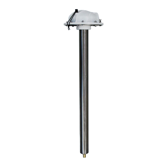
UM022EN M3P / M3P-T / M3P-R BUOYS. User Manual 3.2 Sizes and weights Weight: 1.6 kg Weight: 2.4 kg Weight: 0.4 kg M3P-T Antenna detail Page 5 of 25... -
Page 8: Technical Features
Fuel saving and improvement in the organization of tasks performed on board by means of the longline automatic monitoring. Positioning flash (it can be disabled when programming). Transmission of GPS position and battery level. In M3P-T models, also data on water surface temperature is sent. TEMPERATURE SENSOR Page 6 of 25... - Page 9 UM022EN M3P / M3P-T / M3P-R BUOYS. User Manual They can be fully re-configured (frequency, transmission window, security code, ON/OFF LEDs) through the software designed for that purpose. SECURITY: Encrypted messages. RECHARGEABLE BATTERIES, through the antenna (up to 8 days of operation for M3P, up to 16 days for M3P-T).
-
Page 10: Buoy Reception With Mir2200 Receiver
UM022EN M3P / M3P-T / M3P-R BUOYS. User Manual 3.4 Buoy reception with MIR2200 receiver The buoys transmit the position of the longline by radio. The position is received through the vessel’s HF receiver and digitalized by the MIR2200 equipment. Messages are interpreted by the MSB Palangre software, which represents the longline on the screen. -
Page 11: Buoy Reception With Mir5000 Receiver
UM022EN M3P / M3P-T / M3P-R BUOYS. User Manual 3.5 Buoy reception with MIR5000 receiver The buoys transmit the position of the longline by radio. The position is received through the MIR5000 receiver, which transmits the messages to the MSB Palangre software, which represents the longline on the screen. -
Page 12: Buoy Representation In Msb Palangre
UM022EN M3P / M3P-T / M3P-R BUOYS. User Manual 3.6 Buoy representation in MSB PALANGRE An example of the longline representation in the MSB Palangre is shown below. LINE BREAKS LOW BATTERY BUOYS BUOYS DRIFT VESSEL ROUTE Page 10 of 25... -
Page 13: First Use Of M3P And M3P-T Buoys
UM022EN M3P / M3P-T / M3P-R BUOYS. User Manual 4 FIRST USE OF M3P AND M3P-T BUOYS To start using the buoys, follow these steps: STEP 1. Install the reception equipment (MIR5000 or MIR2200) and the MSB Palangre software on your computer. - Page 14 UM022EN M3P / M3P-T / M3P-R BUOYS. User Manual If the buoy data entered is incorrect, the buoy will not be displayed on the chart. Both with MIR5000 or MIR2200, data may be entered automatically. Refer to MSB Palangre User Manual.
- Page 15 UM022EN M3P / M3P-T / M3P-R BUOYS. User Manual Example of buoy window after buoy data is entered: 26.145 Page 13 of 25...
- Page 16 UM022EN M3P / M3P-T / M3P-R BUOYS. User Manual STEP 2. Place the buoy in a clear location. STEP 3. Remove the magnet to turn it on. STEP 4. Check the green, red and white flashes. The flash can be enabled or disabled through the buoy reprogramming.
- Page 17 UM022EN M3P / M3P-T / M3P-R BUOYS. User Manual BUOY RECEIVED BUOY NOT RECEIVED The buoy is in normal operation when only the white LEDs are on and blinking. The longline buoys within the same system should transmit positions in the same transmission interval to ensure that no position is lost.
-
Page 18: Battery Recharge
The M3P and M3P-T buoys are powered by rechargeable batteries which provide approximately 8 days of operation for the M3P and 16 days for the M3P-T with transmissions every 10 minutes. Battery life varies depending on the selected transmission interval. - Page 19 UM022EN M3P / M3P-T / M3P-R BUOYS. User Manual 2. In the buoy list or clock: The name of the low battery buoy will appear in red. 3. In addition to the low battery warning icons, a message for each low battery buoy will be...
-
Page 20: Buoy End-Of-Charge Led
5.2 Buoy end-of-charge led M3P and M3P-T buoy electronic board includes an improvement in their battery protection, avoiding their overcharge and so extending their life. These protections might make the chargers end-of-charge led false the real state of the buoy battery charge. -
Page 21: Single Charger
UM022EN M3P / M3P-T / M3P-R BUOYS. User Manual 5.3 Single charger Every M3P or M3P-T buoy is delivered with a single charger which stops charging when it detects the battery is fully charged. Single charger for M3P and M3P-T buoys It recharges batteries through the antenna (red crocodile clip to the antenna, and black crocodile clip to the longest screw on the buoy cover). - Page 22 UM022EN M3P / M3P-T / M3P-R BUOYS. User Manual Red crocodile clip to the antenna. Buoy turned off (magnet placed). Black crocodile clip to buoy long closing screw. Page 20 of 25...
-
Page 23: Mip-C Smart Charger
UM022EN M3P / M3P-T / M3P-R BUOYS. User Manual MIP-C Smart Charger MIP-C Smart Charger (optional) enables simultaneous and independent charging of 4 M3P / M3P-T buoys. With the smart charging process, the user does not need to remember to charge the buoys. Once the buoy has been... -
Page 24: M3P And M3P-T Buoy Programming
UM022EN M3P / M3P-T / M3P-R BUOYS. User Manual M3P AND M3P-T BUOY PROGRAMMING The M3P and M3P-T buoys are shipped with a default configuration indicated on the card included with the buoy (transmission frequency, interval between messages, security code, and window). These data can be modified by reprogramming the buoy through the antenna. - Page 25 UM022EN M3P / M3P-T / M3P-R BUOYS. User Manual 1. Connect the PROGRAMMER following the connection diagram shown above (red crocodile clip to the antenna, black crocodile clip to the buoy long closing screw). 2. The buoy should be turned off (magnet in place).
- Page 26 UM022EN M3P / M3P-T / M3P-R BUOYS. User Manual 4. Select M3P buoy model. 5. Connect the programmer to the computer, select port and click on Synchronize. The following message will be displayed: 6. Switch the buoy on (the buoy should be synchronized to be programmed).
- Page 27 UM022EN M3P / M3P-T / M3P-R BUOYS. User Manual If current buoy data needs to be obtained, click on “Get current configuration”. 26145000 Enter the new data and “Send configuration” To check the configuration, go back to “Get current configuration”.
- Page 28 UM022EN M3P / M3P-T / M3P-R BUOYS. User Manual Marine Instruments S.A. states, under its own responsibility, that this device complies with the provisions of Directive 99/05/EC of the European Parliament and Council of March 9 1999, transposed to the Spanish law through Royal Decree 1890/2000, of November 20.
Need help?
Do you have a question about the M3P-T and is the answer not in the manual?
Questions and answers