Table of Contents
Advertisement
Quick Links
Advertisement
Chapters
Table of Contents

Subscribe to Our Youtube Channel
Related Manuals for Brouwer RoboMax


Summary of Contents for Brouwer RoboMax
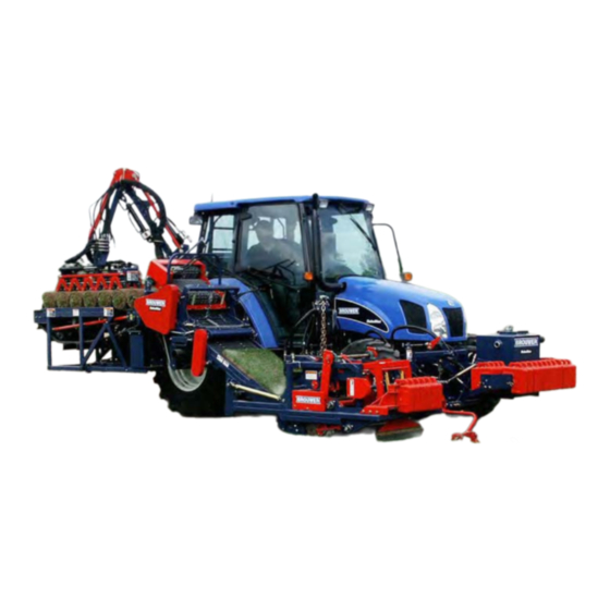
- Page 1 BROUWER SOD HARVESTER Model: 4132506. New Holland OPERATOR’S MANUAL Brouwer Turf 23324 Woodbine Avenue, Keswick Ontario Canada L4P 3E9 Tel (905) 476-6222 Fax (905) 476-6744 Web Site www.brouwerturf.com info@kesmac.com KM99173 April 2017 Revision D...
- Page 3 Turf Harvester Operator’s Manual Contents Foreword Section 1. Safety Section 2. Controls Section 3. Operation Section 4. Maintenance/Lubrication Section 5. Adjustments Section 6. Auto-Steer...
- Page 5 WARNING The Brouwer Robomax Turf Harvesters are designed for safe efficient operation and must not be used for any purpose other than that for which they are designed. Prior to being shipped from the manufacturer the machines are inspected to insure that all safety guards, shields and warning/safety/operating decals are correctly positioned and secure Before operating the machine the operator must check that all of the above items are correctly located.
-
Page 7: Table Of Contents
SAFETY SECTION 1 Safety Symbols Safe Operation General Operating Safety 1-3/1-4 Maintenance Safety 1-4/1-6 Transport and Storage Safe Service Procedure Tire Service Handling Chemicals Safe Welding Safety Warning Decals 1-9/1-11... - Page 9 • BECOME ALERT ! Brouwer Engineering Department. Your safety and that of others is involved. Any Brouwer product that is altered or modified in anyway that is not authorized, after original Signal word definitions. manufacture, including after market accessories or...
-
Page 10: Safe Operation
The warning/safety decals must be kept clean, legible, and undamaged. Do not operate the Read the RoboMax Operation and Safety Manual, and machine if any decals are missing or damaged. also the tractor operating manual. They must be kept on Obtain new decals from the factory. -
Page 11: General Operating Safety
SAFETY General Operating Safety • Ensure all persons are clear of the machine Transporting before starting the tractor engine. Keep hands and feet clear of the cutting unit and all moving • Exercise caution when loading or unloading the parts. machine on or off a truck or trailer. -
Page 12: Maintenance Safety
‘no load’ for five to ten minutes, to allow the engine to cool down. • To attain maximum safety and the optimum harvesting results, maintain your RoboMax To safely park the machine: Harvester according to the recommended schedules and instructions in this manual. - Page 13 Do not support the machine on cinder blocks, hollow tiles, or props that may crumble under WARNING continuous load. The RoboMax Hydraulic System operates under Do not work under a machine that is supported high pressure. solely by a jack.
- Page 14 SAFETY Cooling System If acid is swallowed: WARNING • Do not induce vomiting To prevent serious injury from hot coolant • Drink large quantities of water or milk, but do and steam, DO NOT remove the radiator not exceed 2 liters (2 Quarts). cap when the engine is running and/or hot.
-
Page 15: Transport And Storage
SAFETY Transporting and Storage CAUTION Operating the machine with loose wheel lug nuts • will result in damage to, and require the replace- If the machine should become disabled, and ment of, wheel assembly components. cannot be moved under its own power, it should not be towed, as it would be extremely •... - Page 16 SAFETY • Before disposing of waste material, enquire at your local environmental or recycling facility for instructions on proper waste disposal. Welding on Painted Areas CAUTION Hazardous fumes are generated when paint is heated when welding, soldering, or using a torch. The use an approved respirator is recommended when welding, sanding or grinding on painted areas, to avoid the inhalation of fumes or dust.
- Page 19 D001-222...
- Page 21 CONTROLS SECTION 2 Cab Controls E-Stop Auto-Steer Controls Cutter Blade Main Conveyor LED. Counter Depth of Cut Main Conveyor Lift Manual Over-Ride Controls Control Panel and Screen Initial Start Stacking Pattern Selection Inactive Stacking Active Stacking Step Sequence Active Pallet – Full Inactive Pallet –...
-
Page 23: E-Stop
CONTROLS NOTE All Harvester operating controls, except for Depth of Cut, Conveyor Lift, and Auto-Steer Fine Adjustment, are on the Control Console at the right hand side of the operator’s seat. Harvester E-Stop Switch The keyed E-Stop Switch ‘A’ in the ‘OUT’ position enables all harvester functions except: Travel, Depth of Cut, and Cutter Head position. -
Page 24: Depth Of Cut
CONTROLS Depth-of-Cut The Depth of Cut Adjustment Lever ‘P’(green), is located to the right of the operator’s seat. ‘Increase’ the depth-of-cut: move the lever ‘rearward’. ‘Decrease’ the depth-of-cut: move the lever ‘forward’. A depth of cut indicator ‘Q’, on the Cutter Head acts as a guide when making adjustments to the depth-of-cut. -
Page 25: Initial Start
CONTROLS Control Panel Screens Initial Start Screen The Initial Start Screen is displayed when the tractor ignition key is switched to ‘ON’. • Press Pad ‘1’, to start the Controller and bring up the Stacking Pattern Selection Screen, after the flashing red ‘WAIT’... -
Page 26: Active Stacking
CONTROLS Inactive Stacking Screen The Inactive Stacking Screen is displayed during Initial Start-up. IMPORTANT Do not press any control panel pads until the Active Stacking Screen is displayed. The Inactive Stacking Screen will also be displayed when the stacking sequence is stopped. •... -
Page 27: Step Sequence
CONTROLS Active Stacking screen The Active Stacking Screen is displayed during the stacking sequence. • Press Pad ‘1’ (stop), to stop the stack- ing sequence, and display the Inactive Stacking Screen. • Press and hold, for three seconds, Pad ‘3’, (reset pallet counter) to reset the counter to zero. -
Page 28: Active Pallet - Full
CONTROLS Active Pallet Full Screen The ‘Active Pallet Full’ Screen is automatically displayed when the pallet is full. • Press Pad ‘1’ (Stop), to display the Inactive Pallet Screen. • Press Pad ‘2’ (Empty Pallet), to indicate a new pallet. An empty pallet will be displayed and pallet roll quantity is reset to zero. -
Page 29: Inactive Pallet - Full
CONTROLS Inactive Pallet Full Screen The Inactive Pallet Full Screen is displayed when the Pad ‘1’ (Stop) is pressed on the Active ‘Pallet Full’ Screen. • Press Pad ‘1’ (Start), to return to the Active Pallet Full Screen. • Press Pad ‘2’ (Move Manually), to display the Move Manually Screen. -
Page 30: Manual Mode
CONTROLS Manual Mode Screen When the Move Manually Screen is selected, the system allows the operator to Operate the Robotic Arm, and the Gripper Head, using the Control Levers located at the left rear of the machine. The Pallet Lift Forks ‘Lift’ and ‘Lower’ functions are controlled from the Screen. -
Page 31: Pallet Dispenser
CONTROLS Pallet Dispenser Screen 1. • When the Pallet is ‘full’ and ‘Pallet Full’ is displayed on the screen, press the ‘Right’ Arrow ‘A’ (Pallet Down), and hold down until the pallet is completely ‘down’. • Move the Harvester forward, for two more cuts, then stop the Harvester forward travel and press Pad ‘1 ‘STOP’. - Page 33 OPERATION SECTION 3 Travel Speeds Harvester Conveyor 4 Inch Feed Roller Starter Tray Starter Gate Roll-Up Conveyor Index Conveyor Roll Flap – Stabilizer ‘Bad Roll’ Ejection Robotic Arm Gripper Head Pallet Lift Forks Pallet Dispenser Pallet Specification Pre-Operation ‘Warm-Up’ Procedure Operating Instructions 3-7/3-9...
-
Page 35: Travel Speeds
OPERATION TRAVEL SPEEDS The Brouwer RoboMax Sod harvester is fitted to a RANGE GEAR TRAVEL SPEED (Kph./mph) New Holland TLA Series tractor, built to Brouwer specifications specifically for sod harvesting. 1.3 ( 0.82) 2.0 (1.23) The RoboMax Harvester can be specified with 2.8 (1.74) -
Page 36: Harvester Conveyor
OPERATION Harvester Conveyor CAUTION Safety Guards may have been removed for clarity. Do not operate the Harvester with safety guards missing or damaged. To do so could result in serious personal injury. 4 inch Feed Roller The four inch Roller ‘A’ assists in feeding the sod into the Starter Tray. -
Page 37: Roll-Up Conveyor
The Index Conveyor ‘C’, is synchronized to the Main Conveyor, Robotic Arm and Bad Roll ‘Ejection’. When a Roll is ready to be deposited onto the Index Conveyor, a signal from the RoboMax Controller causes the Index Conveyor to roll back ‘one position’, to accept the completed roll. -
Page 38: Robotic Arm
OPERATION Robotic Arm and Gripper Head The functions of the Robotic Arm ‘A’ are controlled by a Computer Controller, through Proportional Valves. The Proportional Valves Stack Manifold is located on the left rear fender. The Controller provides positioning co-ordinates for: •... -
Page 39: Pallet Dispenser
OPERATION Pallet Dispenser DANGER Keep all bystanders clear, do not allow anyone to enter between the Pallet Dispenser and the Harvester. To do so could result in serious injury or death. Operating Position The Pallet Dispenser is located at the rear left side of the Harvester. -
Page 40: Pre-Operation Warm-Up Procedure
Before operating the machine for harvesting it is important that the Hydraulic Oil is brought up to operating temperature. If the ambient temperature is below 75 deg. F, proceed as follows. • Start the Tractor Engine and switch the RoboMax System Power ‘ON’. •... -
Page 41: Operating Instructions
OPERATION Operating Instructions. NOTE • Lower the Cutter Head by moving the Main Refer to the Controls Section for the ‘Controls Conveyor Control Lever ‘FORWARD’, until the Functions’ instructions. Conveyor Lift Chain is ‘slack’. IMPORTANT CAUTION The Conveyor Lift Cylinder Safety Lock must be Before starting to cut the field, ensure that all by- released before lowering the Cutter Head. - Page 42 OPERATION …cont Stacking Sequence. Transmission Operating Ranges. IMPORTANT Do not ‘stop’ or ‘slow’ the engine while stacking • Select the required transmission configuration, using the ‘Range’ and ‘Shift’ Levers, located to When the 40, 50, 60 or 70 Roll, depending on the pallet the right of the operator’s seat.
- Page 43 The operation of the Robomax Harvester is straight- If ‘forward travel’ was stopped, after the stacking sequ- forward, however, variations in sod rolls and in the local ence was stopped, it may be necessary to ‘manually’...
- Page 45 MAINTENANCE SECTION 4 Maintenance. Maintenance Schedule Hydraulic System Hydraulic Oil Specification Hydraulic Oil Filters Manifolds and Valve Stacks Main Motor Manifold Index Conveyor - Flow Control Orifice replacement Gripper Head/Pallet Lift Forks Manifold Proportional Valves Stack Conveyor Lift Safety Lock Cutter Drive .
- Page 47 FIRST EVERY EVERY EVERY EVERY Maintenance Procedure DAILY HOURS HOURS HOURS HOURS ENGINE. Refer to the Tractor Manufacturers Manual for additional maintenance information and instructions. Check/Top-off Engine Coolant Level. Check/Top-off Engine Oil Level. Check for Water/Oil Leaks. Clean Air Intake Screen. Clean Radiator Cooling Fins.
- Page 48 10,000 + same characteristics, if HYDREX XV is not available. Min. Start-up Temp. Deg.C/Deg.F -40/-40 The RoboMax Hydraulic System uses a three section Hydraulic Pump ‘A’, to supply hydraulic power to the Operating Range. Deg.C -18 to 75 Cutter Head, the Conveyors, Pallet Lift, and the Deg.F...
- Page 49 MAINTENANCE Hydraulic System. High pressure Filter. For additional protection to the Proportional Valves, that control the Robotic Arm, a High Pressure Filter ‘A’, is installed between the Hydraulic Tank and the Proportional Valves. It is mounted on the left side of the tractor, aft of the left front wheel.
-
Page 50: Hydraulic System
MAINTENANCE Hydraulic System. Manifolds and Valve Stacks. Main Motor manifold. The Main Motor Manifold ’A’, is located on the right side of the tractor between the Conveyor and the Tractor. The Motor Manifold receives approximately 15 gallons per minute from the ‘center’ section of the Hydraulic Pump. -
Page 51: Proportional Valves Stack
MAINTENANCE Hydraulic System. Proportional Valves Stack. The Proportional Valve Stack Assembly is mounted above the left rear wheel. It receives approximately 30 gallons per minute from the ‘rear’ section of the Hydraulic Pump. The oil flow is directed through four of the valves, to the Hydraulic Cylinders that control the functions of the Robotic Arm. -
Page 52: Conveyor Lift Safety Lock
MAINTENANCE Conveyor Lift Safety Lock. WARNING To prevent possible serious injury the Conveyor Lift Cylinder Lock must be in place when working on the Cutter Head in the raised position. CAUTION To prevent possible damage to the machine, when the Cutter Head is raised for transport, the Conveyor Cylinder Lift Cylinder Lock must be in place. - Page 53 MAINTENANCE Cutter Drive Belt – Remove/Install. • Pull the Cutter Arm ‘F’ ‘back’. Remove the top section of the Connecting Rod Bearing Cap, and allow the Connecting Rod ’G’ to swing ‘downwards’. • Remove the Nuts ‘H’ from the Crankshaft Bearing Bolts.
-
Page 54: Crankshaft Assembly
MAINTENANCE To Service Crankshaft/Connecting Rods Assembly. Remove Crankshaft Assembly To remove the Crankshaft/Connecting Rods Assembly, follow the instructions for removing the Drive Belt, as shown on pages 4-6 and 4-7. (16/18 in.ass’y.shown). From that point proceed as follows: • Remove the left hand Connecting Rod Bearing Cap ‘A’... - Page 55 MAINTENANCE Crankshaft Bearings and Sheave. To remove the Crankshaft Bearings: • Remove the Connecting Rods. See page4-8. • Back-off the Lock-Collar Set Screw. • Use a suitable Drift or Punch to release the Lock-Collar ‘A’. NOTE Lock-collars are ‘tightened’ in the direction of rotation, and released in the opposite direction.
- Page 56 MAINTENANCE Crank-Shaft Assembly - 24 inch Machine. The Crank-Shaft on 24 inch machines has two Counter Balance Weights ‘A’. They are Keyed to the Shaft and locked with Set Screws. It is necessary to remove one of the Weights if the Driven Sheave needs to be removed.
-
Page 57: Crown Roller
MAINTENANCE Main Conveyor Mat The Rubber Conveyor Mat was initially used in areas with abrasive soil conditions, but has proven to work well in a variety of conditions. It is the preferred choice of most Sod Growers. See page 4-12 for the installation of a new Mat and Metal Clip replacement. -
Page 58: Installation
MAINTENANCE Rubber Conveyor Mat. Mat Splices. The Conveyor Mat is joined with Metal Splices. The Mat must be joined with the lower part of the Mat over-lapping the upper part. It is important that any excess portion of the Threaded Stud is broken off above the Nut when the Splice has been installed. - Page 59 MAINTENANCE Conveyor Mat Installation. When the Conveyor Mat has been installed into the Frame and onto the Sprockets, and has been ‘joined’ with Mat Splices, it will be necessary to align the Mat so that it runs ‘parallel’ in the Frame. The Mat is kept in alignment by the Driving Sprockets at the top of the Conveyor, and the Crown Roller at the front bottom of the Conveyor.
-
Page 60: Mintex Metal Mat
MAINTENANCE Mintex Metal Mat There are no replacement parts in the Mintex Mat. Replace it as an assembly. To ensure a long service life, it is important that the Mat Drive Shaft, Idler Shafts, Idler Sprockets and Rollers Assemblies are parallel to each other and correctly set ‘square’... -
Page 61: Roll-Up Conveyor Stops
MAINTENANCE Conveyor Mat Sliders. Rubber Mat. The Conveyor Sliders ‘A’ are made from UHMW Poly- ethylene that does not require lubrication. Their service life will vary, depending up on the soil conditions. At each major service check the Sliders for excessive wear, particularly under the Roll-up Tray. - Page 62 This page left blank. 4-16...
- Page 65 ADJUSTMENTS SECTION 5 Adjustments. Cut-Off Length Cut-Off Sprocket Selection Chart Cut-Off Cam, Return Cam, Return Cam Stop Return Cam Stops Selection Chart Index Conveyor Roll End Sensor. Sensor Flag Setting Cut-Off Blade Depth Adjustment Spring Cam Eccentric Setting Cut-Off Blade Pitch Angle.
- Page 67 ADJUSTMENTS Cut-Off Length Adjustment. WARNING The Safety Lift Lock MUST be in place when working on the Cutter Head in the raised position. Failure to observe this warning could result in Serious injury or death. CAUTION When changing Sprockets, to modify the Cut-Off length, the length of the chain may also have to be changed, particularly when changing from ‘large’...
-
Page 68: Cut-Off Length
ADJUSTMENTS Cut-Off Length. Sprocket Selection Chart. The Sprocket Combinations that are recommended, for various lengths of sod, are approximations. The final choice of Sprockets will best be determined by ‘field trial’. In the spring, when sod tends to be ‘wet’, it ‘stretches’ as it is cut. -
Page 69: Index Conveyor
Fast Lift – For Cut lengths 54 inches to 72 inches. 001799 77.6 Stamped with the letter ‘F’. This is the 001376 *80.0/81.0 ‘Standard’ Cam for Robomax. 001800 85.8 Super Lift – For lengths greater than 72 inches. 015553 90.0 Stamped with the letters ‘FF’. -
Page 70: Cut-Off Blade Depth Adjustment
ADJUSTMENTS Roll End Sensor. The Roll End sequence starts with the Sensor Flag ‘A’ directly in line with the Sensor ‘B’, before the leading edge of the sod has reached the Starter Gate ‘C’. The Roll End Sensor LED on the Cab Control Panel will indicate ‘ON’. -
Page 71: Cut-Off Blade
ADJUSTMENTS Cut-Off Blade If the Cut-Off Blade ‘A’ does not cut ‘completely’ through the sod when the Spring Shaft is in the desired location, reposition the Cut-Off Blade Frame ‘B’ one hole lower on the Cut-Off Frame ‘C’. The Cut-Off Blade depth is reduced over time by wear, and by sharpening. - Page 72 ADJUSTMENTS Pitch Angle – Fine Adjustment. On the left and right hand sides: • Loosen the Eccentrics Clamps Locknuts ‘A’. • Turn the Adjustment Handle ‘B’ to rotate the Eccentric Adjusters ‘C’ to obtain the required amount of pitch angle. •...
-
Page 73: Roll Flap Stabilizer
ADJUSTMENTS Roll-Up Conveyor. The Roll-Up Tray Hanger Chain ‘A’, should be set so that the clearance between the Roll-Up Tray ‘B’, and the Starter Tray ‘C’, is no less than 2 to 2 ½ inches. Roll-Up Sprockets. The Roll-Up Conveyor ‘D’ completes the roll-up after the sod has passed the Starter Tray. -
Page 74: Cutter Head Alignment
ADJUSTMENTS Main Conveyor. Tracking Alignment. WARNING Do not make any adjustments when the tractor engine is running. Failure to observe this warning could result in serious injury or death IMPORTANT The Main Conveyor must be aligned parallel to the tractor. NOTE For clarity the photographs show the Conveyor Pivot Beam during assembly. -
Page 75: Pallet Lift Forks Sensors
‘A3 – Lower’ must be adjusted so that the face of the Sensor is 1 to 3mm. from the Pallet Lift Sensor Flag ‘B’. To adjust the Sensor Flag: • Switch the Robomax System to ‘ON’ • Raise the Lift Forks to the highest position. •... - Page 77 ROBOMAX SECTION 6 AUTO–STEER Set– Up and Operation. CONTENTS Cutting ‘Starting Strip’. Cam Roller and Roller Arm Position 6-1/6-2 Fine Adjust Control Shoe Arm Adjustment Guide Shoe Adjustment Re-Set Cylinder Chain Adjustment ‘Stop Bolt’ Adjustment Tracking Adjustment Sensitivity Adjustment...
-
Page 79: Cam Roller And Roller Arm Position
AUTO-STEER Auto-Steer Set-up and Operation. When the Auto-Steer System has been initially Set-Up, and the machine is ready to commence harvesting, it is important before starting, that the Auto-Steer final set-up is carried out by following the instructions below. Fig.6-01 A starting strip of turf must be cut ‘manually steering’, this creates the turf ‘edge’... - Page 80 AUTO-STEER Cam and Roller Arm Set-Up. The recommended method of setting the Auto-Steer is: • Position the Harvester ‘ready to cut’. • With the Auto-Steer ‘OFF’, cut a strip of turf, for a minimum distance of 20 feet. It must be cut straight. •...
-
Page 81: Fine Adjust Control
AUTO-STEER Fine Adjust Control. As noted in Figure 6-03, the Fine Adjust Control allows the operator to trim the waste strip. It is recommended that it is set-up as follows: Fig.6-08 Set the Fine Adjust Control to its ‘Mid-Point’ by: •... -
Page 82: Guide Shoe Adjustment
AUTO-STEER Guide Shoe Adjustment. Fig.6-11 The Guide Shoe must be correctly adjusted, as follows : • Loosen the Yoke Clamp Bolt and rotate the Guide Shoe until there is ¼ inch clearance between the inside edge of the shoe and the ground. •... -
Page 83: Tracking Adjustment
AUTO-STEER Tracking Adjustment. The recommended method of setting the tracking is : • Position the harvester ‘ready to cut’. • With the Auto-Steer switched ‘OFF,’ cut a strip of turf, for a minimum distance of 20 feet, it must be cut straight. -
Page 84: Sensitivity Adjustment
AUTO-STEER Sensitivity Adjustment CAUTION The Top Lever Arm is under spring tension. Exercise care when removing the Cable Clevis End from the Top Lever Arm, or when loosening the Lever Arm Clamp Bolt Fig.18 On initial set-up, the Cable End from the Sensitivity Valve is attached at the ‘outer’...
Need help?
Do you have a question about the RoboMax and is the answer not in the manual?
Questions and answers