DigiTrak Falcon F5 Quick Start Manual
Hide thumbs
Also See for Falcon F5:
- Operator's manual (86 pages) ,
- Quick start manual (9 pages) ,
- Quick start manual (8 pages)
Table of Contents
Advertisement
Quick Links
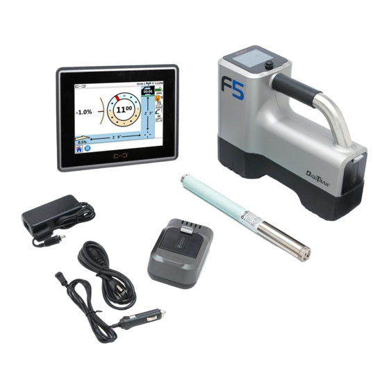
Power On the Receiver
1.
Install the battery pack
and hold the trigger for
one second.
2.
Ensure the region number
in the globe icons on the
startup screen and
transmitter match.
3.
Click trigger to open the Main menu (or toggle down at the
Locate screen).
Receiver Main Menu
Toggle to menu options and click trigger to select;
second page. Use Locate mode for locating.
Transmitter and receiver must be
3
(page
). For DigiTrak remote displays, see separate manual or
© 2018 Digital Control Incorporated, Oct
All rights reserved. 402-1026-24-C metric Russia
1. Telemetry channel
2. Transmitter (Tx) type
3. Tx band up/down
4. Battery strength
5. Locate mode
6. Power off
7. Calibration
8. HAG
9. Settings
10. Tx selection
1. Locate point (ball)
2. Yaw
3. Receiver
4. Roll indicator and value
5. Roll/pitch update meter
6. Transmitter pitch
7. Transmitter signal strength
8. Transmitter fluid pressure
9. Transmitter temperature
Paired
Quick Start Guide.
1. IR port
2. Toggle
3. Trigger
indicates a
before data will display
ru.digital-control.com
- 1 -
Advertisement
Table of Contents

Related Manuals for DigiTrak Falcon F5


Summary of Contents for DigiTrak Falcon F5
- Page 1 8. Transmitter fluid pressure 9. Transmitter temperature Paired Transmitter and receiver must be before data will display (page ). For DigiTrak remote displays, see separate manual or Quick Start Guide. © 2018 Digital Control Incorporated, Oct ru.digital-control.com All rights reserved. 402-1026-24-C metric Russia...
- Page 2 - 2 - Steps Required Before Drilling Optimize and measure active interference. Select frequency bands. Pair the receiver with the transmitter. Check for background noise. Calibrate both bands. Check Above Ground Range. Optimize and Measure Active Interference Transmitter selection With the transmitter off, select from the Main Frequency Optimization menu, then...
- Page 3 - 3 - Your receiver can only detect active interference, not passive interference. Lower frequency bands tend to perform well despite passive interference. Middle bands can perform better in deeper bores and may have longer Target Steering capability. High bands have slightly less signal strength but tend to offer better performance around active interference such as power lines.
-
Page 4: Settings Menu
- 4 - Calibrate Both Bands Calibration in an interference-free environment is required after each optimization. Place the Tx in a housing on level ground 3 m from receiver as shown. Main Calibration From the menu, select > pt calibration and calibrate each new band. Check Above Ground Range (AGR) Always check AGR with a tape measure to verify depth readings on each band at... - Page 5 - 5 - Changing Transmitter Frequency Band Switch between Up and Down bands during pre-bore calibration or mid-bore to overcome interference. See next page to change bands on the receiver. Both optimized bands remain stored on both the receiver and transmitter even after a power cycle.
- Page 6 See the operator's manual if the and signal strength are flashing, indicating extreme interference. ® Watch our DigiTrak training videos at www.YouTube.com/DCIKent For detailed information, see your system operator's manual, available at ru.digital-control.com. If you have questions, contact your regional DCI office at 7.499.281.8177 or U.S. Customer Service at 1.425.251.0559.
- Page 7 - 7 - Basic Locating Find the FLP and RLP by centering the target ball in the box. At the FLP, hold trigger for predicted depth reading. Find the LL by centering the line in the box between the FLP and RLP (see Locate screen on previous page).
- Page 8 - 8 - Bird’s-Eye View on Locate Screen 1. Yaw 2. LL (Tx) 3. Box (receiver) 4. Attenuation 5. Tx 6. Receiver Receiver Locate Screen Actual Position of (Line-in-the-box at LL) Receiver and Transmitter Depth and Predicted Depth Readings Trigger held at LL 1.
Need help?
Do you have a question about the Falcon F5 and is the answer not in the manual?
Questions and answers