
Summary of Contents for stertil ST 1065-FWF
- Page 1 Mobile Column Lift Wireless ST 1065-FWF ST 1075-FWF, FWG ST 1085-FWA, FWG, RWA, RWG, VFWA, VFWG ST 1100-FWA, FWG, RWA, RWG, VFWA, VFWG 38007850 Operation & Service Manual © 2014 Stertil B.V. 38007850...
- Page 2 PLEASE READ AND UNDERSTAND ALL INSTRUCTIONS IN THIS MANUAL BEFORE INSTALLING, OPERATING OR MAINTAINING THIS LIFT. Installation, operating and service instructions for the Stertil- Koni mobile column lifts: ST 1065-FWF ST 1075-FWF, FWG ST 1085-FWA, FWG, RWA, RWG, VFWA, VFWG ST 1100-FWA, FWG, RWA, RWG, VFWA, VFWG Operation &...
-
Page 3: Table Of Contents
Contents Preface About this manual Copyright Limitations of the document Who is this manual intended for? Scope of this manual Document conventions Manufacturers details Guarantee and liability Compliance with standards Trademarks 2.10 Statutory standards and regulations 2.11 Supplements to the manual 2.12 Additional documentation 2.13... - Page 4 Installation Unpacking and setup Switch tube assembly Operation Introduction Safety when hoisting Linking the column lifts Control box 6.4.1 Emergency shutdown button 6.4.2 Starting and identification 6.4.3 Raising 6.4.4 Lowering 6.4.5 Slow lowering 6.4.6 Lowering into the safety locks 6.4.7 Information screen Setting the columns 6.5.1 Operating system 6.5.2 Pair operation...
- Page 5 7.9.12 Weight dimension (optional) 7.9.13 Weight category (optional) 7.9.14 Motor type 7.9.15 Footguard 7.10 Corrective maintenance 7.10.1 General safety requirements for corrective maintenance 7.10.2 Required knowledge 7.10.3 Request for repair 7.10.4 Communication 7.10.5 Spare parts 7.11 Corrective maintenance procedures 7.11.1 Removal and installation of the lifting cylinder 7.11.2 Adjustment of the pallet lifting mechanism 7.11.3 Adjusting the pallet lifting mechanism safety switch 7.11.4 Adjustment of the retractable front wheels (R)
- Page 6 Service sticker 12.2 Electrical connections 12.3 Electrical diagram for control cabinet 12.4 Hydraulics diagram 12.5 Dimensional drawing ST 1065-FWF 12.6 Dimensional drawing ST 1075-FWF 12.7 Dimensional drawing ST 1085-FWA, VFWA, RWA 12.8 Dimensional drawing ST 1100-FWA, VFWA, RWA 12.9 Inspection checklist Index Operation &...
-
Page 7: Preface
PREFACE Prior to the operation of your Stertil mobile column lift, make sure that you read the instructions thoroughly. These instructions are found in this manual. Please note that your warranty can be voided if you do not read the manual and understand its contents. - Page 8 The owner or employer shall establish a periodic preventive maintenance procedure in accordance with the recommendations listed in this manual. Stertil USA shall not be responsible for any actions not specifically called out for in this manual or in this notice.
- Page 9 Thank you for the purchase of your Stertil product. Please contact Stertil USA for the location of authorized Service Centers throughout the United States: Stertil KONI USA Inc. 200 Log Canoe Circle Stevensville, Maryland 21666 tel. 00 1 410 643 9001 fax.
-
Page 10: About This Manual
Limitations of the document This manual is the original English language version. Stertil B.V. reserves the right to modify the construction and/or configuration of its products at any time without any obligation to modify products which have been previously supplied. The data provided in this manual is based on the most recent information. -
Page 11: Who Is This Manual Intended For
Who is this manual intended for? This manual is intended for users and service engineers of the vehicle lift. Anyone who is not familiar with the installation, operation and service of the vehicle lift is advised to fully read the following chapters and to follow the instructions exactly. Personnel that are familiar with the installation, operation and service of the vehicle lift can use this manual for reference. -
Page 12: Manufacturers Details
If you need any assistance, please contact your regional service center. If you still have questions after reading this guide, we would encourage you to contact us. We appreciate all advice, feedback and suggestions from our customers. Please contact Stertil at: Stertil B.V. Address: P.O. -
Page 13: Compliance With Standards
It is the sole responsibility of the purchaser to obey these regulations and laws. 2.11 Supplements to the manual If you receive any supplements to the manual from Stertil, these must be inserted into the manual immediately. 2.12 Additional documentation The vehicle lift contains items of equipment that have not been manufactured by Stertil but that form a part of the installation. -
Page 14: Storing The Manual
Stertil. Also, during the lifetime of the machine, engineering improvements may result in the need to revise this manual. It is then at the discretion of Stertil, if a revision/new version of this manual is required. -
Page 15: Statement Of Conformity
Guide part with suspension eye. The manufacturer is authorized to constitute the technical documentation. Signed, U. Bijlsma, General Manager, authorized for this purpose by Stertil B.V., hereby declares that the vehicle lift as described above, conforms with the fundamental safety requirements as set down in: ... - Page 16 Testing and evaluation has been performed by: INTERTEK TESTING SERVICES NA. Inc., 3933 US Route 11. Cortland, NY 13045 Telephone: 607-753-6711 Fax.: 607-756-9891 WEB: www.intertek-etlsemko.com Under report no.: 3107897CRT-001 Stertil B.V. U. Bijlsma General Manager Date, 01-01-2013 Operation & Service Manual (V0) Wireless...
-
Page 17: Safety
WARNING Always adhere also to the local safety regulations. Stertil B.V. is not liable for damage or physical injury occurring through or owing to the negation of the safety instructions. Stertil B.V. has made all possible efforts to inform you correctly and fully about possible dangers involved in working with this vehicle lift. -
Page 18: Hazards
The supervisor or individual responsible for the work site or organization respectively must ensure that the organization's safety guidelines are strictly followed. WARNING Failure to follow the safety instructions may lead to personal injury and damage to the vehicle lift and vehicle. Hazards This section describes the potential hazards when working with the vehicle lift. -
Page 19: Mechanical Hazards
Keep long hair covered when working around moving mechanical parts. CAUTION Always use spare parts of a type and part number recommended by Stertil. Running a vehicle lift with missing components can cause severe damage. Always make sure that the vehicle lift is complete before attempting its operation. -
Page 20: General Safety Instructions
Always adhere to the local safety regulations. The safety instructions in this manual only serve as a guideline. Stertil B.V. is not liable for damage or physical injury occurring through or owing to the negation of the safety instructions. -
Page 21: The Importance Of Safety
Never operate the vehicle lift when persons, goods and suchlike are on it, under it or in front of it. DANGER Modifications to parts or to the operating system may result in danger for the user. All persons working on the vehicle lift must have free access to the instruction manuals. -
Page 22: Personnel
3.3.4 Personnel Operating, maintenance and repair personnel, as well as anyone who is around this vehicle lift should be aware of the possible dangers. This recommendation applies regardless of other regulations that are issued by a higher authority or included in a (safety) standard. The owner must ensure that employees are qualified to perform the activities involved. -
Page 23: Safety Instructions
Even so, caution is required when using the vehicle lift. Work safely! Stertil has made every effort to inform you as correctly and completely as possible on any dangers associated with operation of the vehicle lift. You must ensure and are responsible for compliance with these behavioral guidelines. - Page 24 To reduce the risk of fire, do not operate equipment in the vicinity of open containers of flammable liquids (gasoline). Provide adequate ventilation when working on internal combustion engines. Keep hair, loose clothing, fingers and all parts of the body away from moving parts. To reduce the risk of electrical shock, do not use on wet surfaces or expose to rain when charging batteries.
- Page 25 Only remove the covers to carry out maintenance, ensure that the vehicle lift is disconnected from the power supply. Take care as burns can occur from touching hot parts. Prevent damage to the power feed cables on account of driving over or heavy or falling objects. Do not operate equipment with a damaged cord or if the equipment has been dropped or damaged until it has been examined by a qualified service...
- Page 26 Use the lifting columns only on a hard and level floor with sufficient bearing capacity, see the specifications for floor pressure and floor load in section Technical specifications. Whenever a vehicle is raised on the lift, always raise the lifts to at least above the first safety lock. Always lower the lifts into the safety lock before starting any work on the vehicle or leaving the vehicle unattended.
-
Page 27: Manufacturers Instructions To The Lift Owner/Employer
3.3.6 Manufacturers instructions to the lift owner/employer The owner/employer shall: Ensure that lift operators are qualified and that they are trained in the safe use and operation of the lift using the manufacturers operating instructions; ALI/SM 01-1, ALI Lifting it Right safety manual; ALI/ST-90, ALI Safety Tips card; ANSI/ALI ALOIM-2008, American National Standard for Automotive Lifts- Safety Requirements for Operation Inspection and Maintenance;... -
Page 28: Safety Features
Safety features The vehicle lift has a control and monitoring system, which ensures that: the guide blocks always stay at an equal height within the control limits, lowering is halted in the event that obstacles cause an elevation difference to occur, ... - Page 29 The next table gives an overview of the various safety signs used on or in the vehicle lift. For each sign the locations where they are fitted are indicated. Pictogram Description Location Capacity sticker At the left and (example). right side of the column.
- Page 30 Pictogram Description Location Caution labels. At the front side above the control box. Warning labels. At the front side above the control box. Safety instruction At the left side of sticker. the column. On this sticker the most important safety instructions are given.
-
Page 31: Lock-Out / Tag-Out
Pictogram Description Location Safety instruction At the operating sticker. side of the column, under the On this sticker the most control box. important safety instructions are given. Electric warning sticker. At the left bottom of the control box. Danger or risk due to electrical voltage. -
Page 32: Lock-Out / Tag-Out Procedure
3.5.1 Lock-out / tag-out procedure Follow the next described procedure to lock-out / tag-out the vehicle lift: Notification. Notify all affected employees that servicing or maintenance is required on the vehicle lift and that the vehicle lift must be shut down and locked out to perform the servicing or maintenance. -
Page 33: Restoring The Vehicle Lift Into Service
Considering the terms of the regulation, Stertil B.V. manufactures articles and is downstream-user of chemical substances. Stertil B.V. has the intention to fully comply to REACH regulation and checked his suppliers to make sure they comply to REACH requirements for all materials and substances used in our products. -
Page 34: Training Levels
Maintenance engineer: Intermediate vocational education level. In case of doubt, always consult the Stertil Service Department. For more information about this and other possible trainings, contact Stertil. Operation & Service Manual (V0) Wireless... -
Page 35: Description
DESCRIPTION Technical specifications The general specifications are also printed on the type plate on the vehicle lift. Model ST1065 ST1075 ST1085 ST1100 Lifting capacity 14,300 lbs 16,500 lbs 18,700 lbs 22,000 lbs Pressure relief valve (sealed 3,045 psi 3,840 psi 3,840 psi 4,280 psi with plastic cap ex-works) -
Page 36: Type Identification
Model ST1065 ST1075 ST1085 ST1100 Length of electrical charging 4' 11'' cable Maximum distance between the approx. 165' column lifts Maximum floor pressure fixed wheels 7,250 psi 7,980 psi 8,700 psi 8,700 psi retractable wheels 870 psi 870 psi Maximum floor loading per front 5,620 lbs 6,520 lbs 7,200 lbs... -
Page 37: Lifting Capacity
Lifting capacity See Technical specifications for specifications of the maximum lifting capacity. The overpressure safeguard in the hydraulic unit has been preset so that the lift can never raise more than the specified weight +10%. Lifting system This mobile column lift is an electrically driven hydraulic column lift for lifting heavy vehicles. -
Page 38: Control System
Control system The control system on the columns ensures that raising and lowering of the column lifts is simultaneous and synchronized, independent of the load distribution on the columns. Each column lift has a potentiometer that detects the height position and passes it on to the control system. -
Page 39: Column, Lifting Cylinder And Guide Block
Column, lifting cylinder and guide block The column and lifting cylinder together form the most important part of the mobile column lift. A guide block with rollers is located within the U-shaped profile of the column. The rollers enable the guide block to move up and down the entire length of the column. -
Page 40: Installation
INSTALLATION Unpacking and setup Proceed as described next when unpacking and setting up each column. WARNING Only use proper lifting equipment to move the column lift. Lift the column only at the points intended for this. Failure to relocate the column lift in the right manner can cause damage to the column lift and/or bodily injury. -
Page 41: Switch Tube Assembly
Switch tube assembly Fit the switch tube (1) onto the pallet lifting mechanism (2) using the bolt, washer and nut. Fit the switch bushing (3) onto the switch tube (1). Refer to section Adjusting the pallet lifting mechanism safety switch (on page 75) for the adjustment. -
Page 42: Operation
OPERATION Introduction The mobile column lifts are designed to provide maximum flexibility and ease of use. A lifting system may consist of 2 to 8 columns in total. The following possibilities are available within the control system: operating all column lifts simultaneously, ... - Page 43 Safety guidelines: When operating an individual column lift, the maximum permissible elevation difference is 2". When operating two column lifts (per-axle control), the maximum permissible elevation difference between the front and rear axles is 6". With a tandem axle at the rear of the vehicle, the maximum permissible elevation difference between both rear axles is 2".
-
Page 44: Linking The Column Lifts
WARNING Lifting one wheel of a floating axle will result in a dangerous horizontal displacement of the column. Hoisting floating axles Linking the column lifts Sets comprising 2 to 8 columns can be put together using a wireless controller. Linking columns together is done through an identification procedure. -
Page 45: Control Box
Control box All functions of the lifting system are controlled from the control box on the column lift. 1. Emergency stop button 2. Information screen 3. UP button 4. DOWN button 5. [SELECT] button 6. [UNLOCK] button 7. Slow lowering selection button 8. - Page 46 Follow the next described procedure to start the vehicle lift: Select an (even) number of columns (2-8) that are jointly to define a set. Check that all the emergency stop switches are unlocked. Place the columns with the forks around the wheels of the vehicle. ...
- Page 47 When the required number of columns have been identified, go to the column that was selected first and hold the ID key in front of the reader there again. This is acknowledged with two bleeps and the green lamp is illuminated continuously.
-
Page 48: Raising
6.4.3 Raising To raise the column lifts, press the [UP] button. There is an arrow pointing up beside this button. 6.4.4 Lowering Operate the [UNLOCK] button simultaneously with the [DOWN] button to lower the column lifts. There is an arrow pointing down next to the [DOWN] button. ... -
Page 49: Lowering Into The Safety Locks
6.4.6 Lowering into the safety locks For lowering onto the safety locks, simply press the [DOWN] button. The column lifts will then lower no more than 1 3/8", until the safety pawls engage the teeth in the safety lock profile. The drop-safeguard pawls can then no longer be released. -
Page 50: Setting The Columns
Column number: Shows the number of the column. Set size: Shows the number of columns in this set. Work timer: This timer is reset and starts to run as soon as the vehicle lift is 2'' from the ground. This can be seen by a blinking colon character. The timer stops again as soon as the vehicle lift is lower than 2''. -
Page 51: Operation Of A Single Column
An acoustic signal will be emitted when "PAIR" UP and DOWN are operational, because this is an unusual situation. When setting up pair operation, the last two remaining columns will automatically be defined as a pair. This means: Set of 4: select 1 pair and the remaining columns automatically become a pair. Set of 6: select 2 pairs and the remaining columns automatically become a pair. -
Page 52: Running Procedures
Running procedures 6.7.1 Preparations before operation Before using the column lift, make sure that: the floor where the column lifts are set up is capable of supporting the setup and the vehicle, the installation has taken account of the need for an escape route at least 2 feet wide on all sides of the setup, ... -
Page 53: Unblocking In Case Of Emergency
Manual lowering may only be carried out by an authorized technician. Traverse beam (option) For the lifting and lowering of trailers on a set of mobile lifting columns, a special Stertil-Koni traverse beam is available. Operation & Service Manual (V0) Wireless... -
Page 54: Outdoor Use
For the operating procedures and safety precautions of the traverse beam, see section Traverse beam (on page 94). Outdoor use When the lifting system is used outdoors, you must take account of the maximum permissible wind speeds. Maximum permissible wind speeds for various types of vehicles are given in the next table. -
Page 55: Adjustable Forks
6.10 Adjustable forks The mobile column lifts can be used for lifting vehicles with a wheel diameter of R10 to R22.5. The forks can be adjusted as follows to obtain the required wheel diameter: Pull the T-shaped handle up to unlock the fork. Slide the fork to the side. - Page 56 Lock the fork by pushing the T-shaped handle again downwards in one of the holes (check this). Wheel positioning Operation & Service Manual (V0) Wireless...
-
Page 57: Inspection And Maintenance
Stertil service department or distributor. If you are allowed to perform an action but are unsure whether you have the ability to do so, please contact your local Stertil service department or distributor. Always observe the safety procedures when carrying out maintenance; see chapter Safety (on page 17). -
Page 58: Recommendations For Maintenance
Do not attempt to operate defective equipment. Follow the safety instructions in this manual. Follow the safety regulations that apply to your site. For repairs and maintenance, always use original Stertil parts. 7.2.2 Preparations before inspection and maintenance Always lower the column lifts completely and switch off the main power switch (position 0) during inspection and maintenance. -
Page 59: Waste Disposal
Turn the main switch to the OFF position and lock it with a padlock. Place a tag "Do not start" at the control box. Please refer to the chapter Safety (on page 17) for an overview of all safety instructions. 7.2.4 Waste disposal Remove and dispose in a correct manner lubricating agents, used chemical... -
Page 60: Annual Maintenance By The Technical Service
If a task cannot be performed correctly, consult the technical service. Annual maintenance by the technical service The user must have the column lifts inspected once a year by the Stertil technical services or another technical service authorized by Stertil (both hereafter referred to as technical services). -
Page 61: Regular Preventive Maintenance Procedures
Regular preventive maintenance procedures 7.6.1 Lubrication instructions The vehicle lifts must be serviced regularly in accordance with the lubrication instructions. Lubrication instructions Every 2 Per year Maintenance years Description Monthly (technical tasks (technical service) service) Cylinder Lubricate dry piston-rod (machine oil). Check oil level in Top up (only with tank... -
Page 62: Hydraulic Oil
7.6.2 Hydraulic oil Replace the hydraulic oil in the tank approximately once every 2 years. This oil change must take place as scheduled, even when the column lift is not being used continuously. When changing the hydraulic oil, proceed as follows: Fully lower the column lifts and drain off the oil. -
Page 63: Checking The Safety Locking Feature
7.6.4 Checking the safety locking feature 1. Guide block 2. Column 3. Adjustment nut 4. Last tooth of locking ratchet 5. Locking ratchet profile 6. Standard 3 notches 7. Potentiometer adjustment rod 8. Potentiometer unit 3 - 4mm Adjusting the safety lock Lower the column lifts completely, if necessary, use the switches S1 through S4 on the control panel;... -
Page 64: Checking The Pneumatic Spring(S)
Now lift one of the columns using the pallet lifting mechanism. The display should now indicate "DISCONNECTING", and then "Column on wheels. Lower column before numbering sequence". Repeat this for all the columns. If the message does not appear, the switch bushing on the switch rod must be adjusted correctly. - Page 65 WARNING Do not use an external battery charger (booster) to charge the batteries. Only use the built-in Stertil-Koni battery charger. Loading the batteries with a standard charger can cause explosive gasses to be produced. Only replace the batteries with original Stertil-Koni batteries.
-
Page 66: Maintenance Switches
Maintenance switches Switches can be found in the control panel that can be operated by the fitter during maintenance to the lifting system. These switches can be used to check whether the lowering valve, the unlocking solenoid and the hydraulic power unit are functioning properly. -
Page 67: Batteries
WARNING Do not use an external battery charger (booster) to charge the batteries. Only use the built-in Stertil-Koni battery charger. Loading the batteries with a standard charger can cause explosive gasses to be produced. Only replace the batteries with original Stertil-Koni batteries. -
Page 68: Height Limit
The [SLOW LOWERING] (turtle) button confirms the choice and exits the service menu. 7.9.1 Height limit If this function is OFF, the vehicle lift stops in the highest position at the fixed value set in the software. The height limit can be programmed as follows: Position the column at the required height. -
Page 69: Height Monitoring
This setting is active for 10 minutes and the height difference guard is then automatically switched back ON again. The height difference monitoring can be switched back ON again from the service menu. This setting is not stored in memory, so height difference guard is always switched ON after the system is switched off and on again. -
Page 70: Language
7.9.8 Language This setting allows the language used on the screen to be selected. There is a choice of: Language settings Setting Language Dutch English German French Spanish Polish Italian Portuguese 7.9.9 Motor run time hours This shows the time (in hours and minutes) that the motor has run for. The time is stored by the controller and cannot be reset. -
Page 71: Weight Dimension (Optional)
7.9.12 Weight dimension (optional) This setting shows the representation of the weight on the screen. The choices are: kg = kilograms lbs = pounds bar = kg/cm system pressure uA = microamps (the measurement range of the pressure transmitter is 0 to 20,000 uA) The load is derived from the hydraulic pressure in the lifting cylinder. -
Page 72: Corrective Maintenance
If necessary, call help from third parties or consult your supplier. 7.10.3 Request for repair If the services of a Stertil engineer are required, it is necessary to have the following information: The serial number of the vehicle lift. -
Page 73: Spare Parts
7.10.5 Spare parts Use only the spare parts as recommended by Stertil. When ordering spare parts, always quote the serial number of the vehicle lift and the item number. 7.11 Corrective maintenance procedures 7.11.1 Removal and installation of the lifting cylinder Proceed as follows to remove the cylinder: At the top of the column lift, remove the plastic cap, nut and washer. -
Page 74: Adjustment Of The Pallet Lifting Mechanism
7.11.2 Adjustment of the pallet lifting mechanism 1. Lever position 1 6. Lever plate (C) 2. Lever position 2 7. Nut 1 3. Lever position 3 8. Adjusting screw 4. Lever 9. Chain 5. Drawbar With the lever in position 3, move the drawbar up and down. If the adjustment is correct, the cylinder should now give about 5/16"... -
Page 75: Adjusting The Pallet Lifting Mechanism Safety Switch
7.11.3 Adjusting the pallet lifting mechanism safety switch Adjusting the safety switch Put the pallet lifting mechanism into its lowest position (lifting column entirely on the floor). Now adjust the switch bushing (3) so that the switch (4) is just not quite activated; see section Switch tube assembly (on page 41). -
Page 76: Adjustment Of The Retractable Front Wheels (R)
Index to the section in this group. Total number of parts in the column lift. Reference The numbers in this column are Stertil B.V. order numbers. Please specify these numbers when ordering. Description This column contains the name of the parts. -
Page 77: Replacement Parts
7.13 Replacement parts You can order replacement parts from Stertil B.V. - see section Manufacturers details (on page 12) for address details. When ordering replacement parts, please supply the following information: Column lift type: Wireless Serial number: See the type plate on the column lift. -
Page 78: Troubleshooting
(and the consequences thereof) are entirely at the user’s own risk. Technical service is taken to mean either the Stertil technical service or another technical service authorized by Stertil. The following troubleshooting guide can be used to identify possible defects. If in doubt, contact technical services. - Page 79 When lowering: The lowering motion stops and the message Down stop limit exceeded appears on the screen. Warning while lowering A height difference of 1 3/16" has arisen between the columns during lowering. Raise the columns approximately 4" and remove any obstacles. The column lifts can now be lowered further.
-
Page 80: Warnings
Warnings Various functions can be locked out when there is a warning. This is shown on the screen as follows: Warning The table indicates how the system can then be brought back to its normal status. Warnings Code Screen text Possible cause Solution Down stop limit... - Page 81 Code Screen text Possible cause Solution Very low More than 15 raise Set the system charging. battery. actions on a single No more battery charge. movements possible. Other column in The service menu is Quit the service program by service menu. open on one of the pressing the [SLOW other columns.
-
Page 82: Error Reports
Error reports When there is an error, further operations are locked out. This is shown on the screen as follows: Error report The error has to be canceled first. Pressing [SELECT] and [UNLOCK] continuously for 2 seconds resets the system. Troubleshooting Code Screen text... - Page 83 Code Screen text Possible cause Solution Output UNLOCK button Check the pushbutton. UNLOCK too stuck. long activated. 10 - 17 Turn off limit Hydraulic leak in Cancel the fault by pressing columns 1 to 8. one of the columns: [SELECT] and [UNLOCK] this can be for 2 seconds.
- Page 84 Code Screen text Possible cause Solution Main relay The main relay may Replace the main relay. active. have stuck. Main relay not The main relay does Replace the main relay. active. not switch on, despite receiving a control voltage. Internal main The main relay on Replace the PCB.
-
Page 85: Fault Messages
Fault messages If there is a fault, the radio network will be canceled and a red light (FAULT) will be continuously illuminated on the front panel. On the screen, it looks like this: Fault message Before the system can be restarted, the fault must be canceled. Fault messages Code Screen text... -
Page 86: Faults
Code Screen text Possible cause Solution Front key. A pushbutton was Reboot. being pressed during startup. ID-key conflict. The ID-key has a Use a different ID-key. code that is not allowed. Hardware An error has Reboot the system. If the failure: occurred on the fault occurs again, contact... -
Page 87: The Column Lift Cannot Be Raised
8.6.1 The column lift cannot be raised Cause Solution No battery power. Check the main fuse above the batteries. Have the batteries checked by a battery specialist. Oil level too low (but motor running). Top up; see Lubrication program. There is air in the hydraulic pump Select [SINGLE] operation and press (only possible if the tank has been the [UP] button until the column lift rises... -
Page 88: The Column Lift Lowers All By Itself
Cause Solution The maximum elevation difference Press [UP] until the height difference (more than 1 3/16") has been has been levelled out. exceeded. If lifting is not required, you can press the [SELECT] button three times. Then you can lower. The difference of 1 3/16" remains. -
Page 89: No Battery Power
Cause Solution The steel plug has not been replaced Fit the air bleed cap. by the air bleed cap. The air bleed cap is blocked. Clean the air bleed cap. 8.6.5 No battery power Cause Solution No battery power. Charge the batteries using the mains cable supplied. -
Page 90: Emergency Lowering Facility
If the tips provided in this chapter do not answer your question or solve your problem, please contact your local Stertil service department or distributor. For a complete list of Stertil distributors and local service departments, please refer to the website of Stertil on the internet: www.stertil.nl Operation &... -
Page 91: Options
OPTIONS Wheel adapters The mobile column lifts may be used to hoist vehicles with wheel diameters ranging from R12 (20") to R22.5 (45"). Wheel adapters must be used for certain wheel diameters. Wheel adapters For tire sizes R12 (20") to R15 (26"), two adapters (A) are needed. For tire sizes R15 (26") to R17 (36"), one adapter (B) is needed. - Page 92 For smaller wheel diameters (< 20"), special adapters are available. Wheel adapters with locking pin WARNING When using wheel adapters (A), always lock the wheel adapters with the locking pin (B). Operation & Service Manual (V0) Wireless...
-
Page 93: Longer Wheel Adapters
9.1.1 Longer wheel adapters Special 6" longer wheel adapters (D, E) can be supplied for hoisting vehicles with double wheels such as trucks, busses, etc. and for vehicles with an overhanging body (camper vans, etc.). Longer wheel adapters WARNING These longer wheel adapters may only be used in combination with the column foot extensions (C). -
Page 94: Traverse Beam
When this is the case, the column foot extensions may remain fitted. Traverse beam For the lifting and lowering of trailers on a set of mobile lifting columns, a special Stertil-Koni traverse beam is available. 9.2.1 Before you start working Check both the maximum lifting capacity of the traverse beam and the maximum lifting capacity of a set of two mobile columns. -
Page 95: Tilting Of The Traverse Beam With King Pin Adapter
Operate the mobile lifting columns as described in section Running procedures (on page 52). 9.2.3 Tilting of the traverse beam with king pin adapter For some trailer models, a traverse beam with a King Pin Adapter must be used. Due to the design of the suspension of trailers, some models will move horizontally when the wheels are touching the ground again. -
Page 96: Guide Part With Suspension Eye
9.2.4 Guide part with suspension eye Special custom made adapters can be delivered. Special guide part with suspension eye Operation & Service Manual (V0) Wireless... -
Page 97: List Of Parts
LIST OF PARTS The following sections will give an overview of the main assemblies and their components. Operation & Service Manual (V0) Wireless... -
Page 98: Main Components
10.1 Main components Operation & Service Manual (V0) Wireless... - Page 99 Part No. Description Remarks 38007800 Mobile column, Battery_Wireless 69800001 Battery 12V/105Ah VDC31M 38007700 Control-wireless 38110200 Guide block ST1075xxF 38320200 Guide block ST1085V-1100VxxA 38220200 Guide block ST1085-1100xxA 38230200 Guide block ST1065-1085- 1100xxG 38130200 Guide block ST1075xxG 38007600 Hydraulic unit, W mod. 38110400 Column ST1075Fxx_1085Fxx 38250400...
-
Page 100: Guide Block St 1075-Xxf
10.2 Guide block ST 1075-xxF Part No. Description Remarks 38110200 Guide piece ST1075xxF 38110201 Guide piece ST1075xxF Weld. assy. 32700104 Caster wheel 30001006 Slide plate blue + groove 16mm / 5/8" 34400600 Hydr. cyl. mount. assy. L=1860 S=1744 D/d=75/50 34200116 Locking bush 1035.46.05.66 Cyl. -
Page 101: Guide Block St 1085-Vxxa / St 1100-Vxxa
10.3 Guide block ST 1085-VxxA / ST 1100-VxxA Part No. Description Remarks 38320200 Guide piece ST1085V-1100VxxA 38320201 Guide piece ST1085V-1100VxxA Weld. assy. 32700104 Caster wheel 30001006 Slide plate blue + groove 16mm / 5/8" 32706800 Hydr. cyl. mount. assy. Mount. assy. 30501003 Shim washer 1036.46.03.45... -
Page 102: Guide Block St 1085-Xxa / St 1100-Xxa
10.4 Guide block ST 1085-xxA / ST 1100-xxA Part No. Description Remarks 38220200 Guide piece ST1085-1100xxA 38220201 Guide piece ST1085-1100xxA Weld. assy. 32700104 Caster wheel 30001006 Slide plate blue + groove 16mm / 5/8" 32706800 Hydr. cyl. mount. assy. Mount. assy. 30501003 Shim washer 1036.46.03.45... -
Page 103: Guide Block St 1065-Xxg / St 1085-Xxg / St 1100-Xxg
10.5 Guide block ST 1065-xxG / ST 1085-xxG / ST 1100-xxG Part No. Description Remarks 38230200 Guide piece ST1065-1085- 1100xxG 38230201 Guide piece ST1065-1085- Weld. assy. 1100xxG 32700104 Caster wheel 30001006 Slide plate blue + groove 16mm / 5/8" 32706800 Hydr. -
Page 104: Guide Block St 1075-Xxg
10.6 Guide block ST 1075-xxG Part No. Description Remarks 38130200 Guide piece ST1075xxG 38130201 Guide piece ST1075xxG Weld. assy. 32700104 Caster wheel 30001006 Slide plate blue + groove 16mm / 5/8" 34400600 Hydr. cyl. mount. assy. L=1860 S=1744 D/d=75/50 34200116 Locking bush 1035.46.05.66 Cyl. -
Page 105: Column St 1075-Fxx / St 1085-Fxx
10.7 Column ST 1075-Fxx / ST 1085-Fxx Operation & Service Manual (V0) Wireless... - Page 106 Part No. Description Remarks 38110400 Column ST1075Fxx / ST 1085Fxx 38110401 Column ST1075Fxx / ST Weld. assy. 1085Fxx 32500109 Wheel axle 32500116 Wheel 32550102 Axle 32700101 Potentiometer bracket 32700116 Height stop Arched 30001004 Clamp plate 32700122 Pawl 69451400 Lifting solenoid 30007400 Potentiometer unit Mount.
-
Page 107: Column St 1085-Rxx
10.8 Column ST 1085-Rxx Part No. Description Remarks 38250400 Column ST1085Rxx 38250401 Column ST1085Rxx Weld. assy. Operation & Service Manual (V0) Wireless... - Page 108 Part No. Description Remarks 32550102 Axle 32700101 Potentiometer bracket 32700116 Height stop Arched 30001004 Clamp plate 32700122 Pawl 32700111 Hinge pivot 32700131 Synthetic guard 32700138 Pressure plate 32700150 Front support Weld. assy. 32700225 Cylinder hinge Weld. assy. 32700129 Axle hinge Pallet mech 32700200 Pallet mech.
- Page 109 Part No. Description Remarks 32700160 Drawbar Weld. assy. 32700110 Wheel axle 65725009 L. cyl. head screw/hex. socket SS 70 DIN7984 M10x20 66103908 Bearing bush GFM-1214-10 Igus 66103909 Groove ball bearing 60052RSR Operation & Service Manual (V0) Wireless...
-
Page 110: Column St 1085-Vfxx / St 1100-Vfxx
10.9 Column ST 1085-VFxx / ST 1100-VFxx Operation & Service Manual (V0) Wireless... - Page 111 Part No. Description Remarks 38510400 Column ST 1085VFxx/1100VFxx 38510401 Column ST 1085VFxx/1100VFxx Weld. assy. 32500109 Wheel axle 32500116 Wheel 32550102 Axle 32700101 Potentiometer bracket 32700116 Height stop Arched 30001004 Clamp plate 32700122 Pawl 69451400 Lifting solenoid 30007400 Potentiometer unit Mount. assy. 66201085 Shock-absorbing cap Skiffy 070012000007...
-
Page 112: Column St 1100-Fxx
10.10 Column ST 1100-Fxx Operation & Service Manual (V0) Wireless... - Page 113 Part No. Description Remarks 38410400 Column ST1100Fxx 38410401 Column ST1100Fxx Weld. assy. 32500109 Wheel axle 32500116 Wheel 32550102 Axle 32700101 Potentiometer bracket 32700116 Height stop Arched 30001004 Clamp plate 32700122 Pawl 69451400 Lifting solenoid 30007400 Potentiometer unit Mount. assy. 66201085 Shock-absorbing cap Skiffy 070012000007 69090050...
-
Page 114: Column St 1100-Rxx
10.11 Column ST 1100-Rxx Operation & Service Manual (V0) Wireless... - Page 115 Part No. Description Remarks 38450400 Column ST1100Rxx 38450401 Column ST1100Rxx Weld. assy. 32550102 Axle 32700101 Potentiometer bracket 32700116 Height stop Arched 30001004 Clamp plate 32700122 Pawl 32700111 Hinge pivot 32700131 Synthetic guard 32700138 Pressure plate 32700150 Front support Weld. assy. 32700225 Cylinder hinge Weld.
- Page 116 Part No. Description Remarks 65760012 Retaining ring a12 SS DIN471 32700105 Wheel 32700170 Hinge Weld. assy. 32700160 Drawbar Weld. assy. 32700110 Wheel axle 65725009 L. cyl. head screw/hex. socket SS 70 DIN7984 M10x20 66103908 Bearing bush GFM-1214-10 Igus 66103909 Groove ball bearing 60052RSR Operation &...
-
Page 117: Pallet Lift Mechanism
10.12 Pallet lift mechanism 250-2 Part No. Description Remarks 38000113 Pallet lift mechanism 250-2 32700250 Tilt beam Weld. assy. 32550103 Axle 32700120 Bearing head 32706200 Pallet truck mechanism HU-lift HP20S 32700910 Gas spring 14/28 s=64 With fork and retainer 66201055 Spacer bushing 12.8 18-15 skiffy nr. - Page 118 10.13 Pallet lift mechanism 300-2 Part No. Description Remarks 38000112 Pallet lift mechanism 300-2 32700300 Tilt beam ST 1082-F/BAT Weld. assy. 32550103 Axle 32700120 Bearing head 32706200 Pallet truck mechanism HU-lift HP20S 32700910 Gas spring 14/28 s=64 With fork and retainer 66201055 Spacer bushing 12.8 18-15 skiffy nr.
-
Page 119: Fork Arms St 1085
10.14 Fork arms ST 1085 Part No. Description Remarks 38220300 Fork set ST1085-350-long 32702075 Adjustable fork (left) welding assembly 32702085 Adjustable fork (right) welding assembly 32700118 Arm lock 66201102 Handle, elesa-T-griff L.652/80 B-M8 nero 32456 65012443 Cyl. head screw M12x20 8.8 DIN912 GV 60201703 Pressure spring 304820... -
Page 120: Fork Arms St 1100
10.15 Fork arms ST 1100 Part No. Description Remarks 38420300 Fork set ST1100-300-long 38420301 Fork left-300 38420302 Fork right-300 32700118 Arm lock 66201102 Handle, elesa-T-griff L.652/80 B-M8 nero 32456 65012443 Cyl. head screw M12x20 8.8 DIN912 GV 60201703 Pressure spring 304820 Bakker Operation &... -
Page 121: Drive Unit B/W
10.16 Drive unit B/W Part No. Description Remarks 38007600 Hydro unit, W mod. 68038... Hydr. unit ... bar corr. 24VDC/1,2/-/2/9 32736150 Hydr. hose L=900 Battery version 32706075 Oil line mount. assy. 68700450 Straight screw coupling GE 10-PSR 65003403 Hex. head screw M10x20 8.8 DIN933 GV 65003285 Hex. -
Page 122: Hydraulic Unit
10.17 Hydraulic unit Operation & Service Manual (V0) Wireless... - Page 123 Part No. Description Remarks 68038421 Hydr. unit 1.2cc, 24V 3,000 psi ST 1065 68038427 Hydr. unit 1.2cc, 24V 3,840 psi ST 1075, ST 1085 68038429 Hydr. unit 1.2cc, 24V 4,280 psi ST 1100 68039011 Tank plastic 10 liter 68510911 O-ring 110.72x3.53 mm 32506103 Suction filter D.62 dia.
-
Page 124: Hydraulic Cylinder
10.18 Hydraulic cylinder Operation & Service Manual (V0) Wireless... - Page 125 Qty Part No. Description Remarks 34400600 Cylinder (assembly) Cylinder bottom O-ring Ø56,74x3,53 Backup ring Retaining ring Piston seal Bearing ring O-ring Ø34x3 Backup ring Piston Cylinder Piston rod Guide post Bearing ring Piston cap 68228005 Hose burst check valve 68700451 Union GE 10-PSR 1/4"...
-
Page 126: Hydraulic Cylinder
10.19 Hydraulic cylinder Operation & Service Manual (V0) Wireless... - Page 127 Part No. Description Remarks 32706800 Cylinder (assembly) Bearing ring Backup ring O-ring Bearing ring Piston seal O-ring Backup ring Piston cap 68700450 Straight adaptor 1003.91.80.38 Hose burst check valve 68900000 Air bleeding nipple Cylinder Piston rod Piston Gate Retaining ring 65263009 Spring ring Cylinder bottom...
-
Page 128: Control Unit W
10.20 Control unit W Part No. Description Remarks 38007700 Control - wireless 38006101 Box, battery versions 32500108 Bracket 32730251 Drawbar Screen cabinet 32739100 Control box Wireless/Bat 32730254 Inspection glass Meanwell battery charger 69206403 Fuse block Mount. assy. Operation & Service Manual (V0) Wireless... - Page 129 69206102 Fuse 200A 300V A3T200 Ferraz Shawmut 69302016 Connector plug PX0580/63 Black (Bulgin) 69500104 Battery charger 110/230V-24V PB-300P-24 MeanWell 69120026 Battery switch 443.782.0 ASA BOOT 1002.22.01.32 Grommet int.6,4 Skiffy 042060169907 3010010 Schwingmetall parabolic spring number 58497 65074216 Cotter pin 4x32 DIN94 GV 65032168 Galv.
- Page 130 1038.13.50.01 Self-adhesive cable clamp viba 13805/834 (80668) 38006105 Hinge 38006108 Box closure 38006111 Switch support 66201026 Self-adh. clip skiffy nr.1140002 65055414 Flat washer M6 DIN9021 65058018 Spring washer M6 DIN127B GV Operation & Service Manual (V0) Wireless...
-
Page 131: Control Box
10.21 Control box Operation & Service Manual (V0) Wireless... - Page 132 Part No. Description Remarks 32739100 Control box battery/wireless 69900160 PCB battery/wireless 32739050 Foil covered switch panel 69120018 Emergency stop and lock 69120019 Contact element + bridge 69120020 Contact element + breaker 69120021 Sticker yellow 69202009 Acoustical alarm 69062008 Cable gland M20x1.5 69062063 Cable gland M25x1.5 69062041...
-
Page 133: Labels Wireless Version Us
10.22 Labels wireless version US Operation & Service Manual (V0) Wireless... - Page 134 Capacity sticker 16500 lbs 60700352 Capacity sticker 18500 lbs 60700145 Capacity sticker 22000 lbs 60700061 STERTIL KONI 60700090 Stertil Koni USA 60700092 Sticker Caution 60700093 Sticker Warning 60700133 Sticker If connected 60700134 Sticker Do not use 60700226 Sticker Control 60700189...
-
Page 135: List Of Parts - Variants And Options
LIST OF PARTS - VARIANTS AND OPTIONS Operation & Service Manual (V0) Wireless... -
Page 136: Wheel Adaptors And Extended Column
11.1 Wheel adaptors and extended column Operation & Service Manual (V0) Wireless... - Page 137 Part No. Description Remarks 32700920 Wheel adaptor 14" Right 32700925 Wheel adaptor 14" Left 34200930 Longer wheel adaptor 20" Right Max. 8,800 lbs 34200935 Longer wheel adaptor 20" Left Max. 8,800 lbs 3bR* 34400930 Longer fork adaptor Right Max. 14,500 lbs 3bL* 34400935 Longer fork adaptor Left...
-
Page 138: Traverse Beam
11.2 Traverse beam Type: 32591100 Part No. Description Remarks 32591100 Traverse beam 32591054 Traverse beam support 66002015 Wheel 60700164 Capacity sticker See previous table. 65003408 Hex. cap screw M10x35 8.8 DIN 933 GV 65058028 Circlip M10 DIN127B GV 65050134 Hex. nut M10 8 DIN934 GV 32591020 Adapter adjustable 32591051... - Page 139 Description Remarks 32591500 Traverse beam 32591510 Traverse beam support 32591020 Adapter adjustable 1020.50.00.30 Wheel 1038.40.04.00 Retaining ring A40 DIN471FF 1005.01.01.49 Stertil-Koni sticker 60700127 Capacity sticker 14400 kg / 32,000 lbs 60700102 Stertil-Koni sticker (medium) Operation & Service Manual (V0) Wireless...
- Page 140 King pin support 32500116 Wheel 1038.34.02.40 Retaining ring No.24 DIN6799 GV 4310.09.00.10 Pin with clip 32592005 Reducing bush 3,5 to 2 60700102 Stertil-Koni sticker 60700075 Capacity sticker 7200 kg 60700076 Capacity sticker 16000 lbs Operation & Service Manual (V0) Wireless...
-
Page 141: Appendices
APPENDICES 12.1 Service sticker Service sticker The service sticker is behind the control cabinet. The items stated on the sticker include the type of main fuse used and how the various components on the controller PCB are connected. Operation & Service Manual (V0) Wireless... -
Page 142: Electrical Connections
12.2 Electrical connections 1. Control cabinet 9. Charging cable 2. Relay (24V/150A) 10. Relay-motor cable 3. Battery charger 11. Switch-fuse cable 4. Main switch 12. Pos. battery terminal-switch cable 5 Fuse holder 13. Neg. battery terminal-pos. battery terminal cable 6. 200A main fuse 14. -
Page 143: Electrical Diagram For Control Cabinet
12.3 Electrical diagram for control cabinet Electrical diagram for control cabinet Operation & Service Manual (V0) Wireless... -
Page 144: Hydraulics Diagram
12.4 Hydraulics diagram Hydraulics diagram Item Description Torque Cylinder EV22 2/2 valve 22 lbf VCDF Flow control valve F1/F2 Filter Non-return valve 16.5 lbf Pump 16.5 lbf Tank Safety pressure valve 18.4 lbf Electric motor Hose burst check valve Operation & Service Manual (V0) Wireless... -
Page 145: Dimensional Drawing St 1065-Fwf
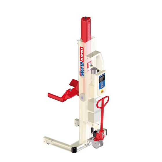
12.5 Dimensional drawing ST 1065-FWF Dimensional drawing ST 1065-FWF Operation & Service Manual (V0) Wireless... -
Page 146: Dimensional Drawing St 1075-Fwf
12.6 Dimensional drawing ST 1075-FWF Dimensional drawing ST 1075-FWF Operation & Service Manual (V0) Wireless... -
Page 147: Dimensional Drawing St 1085-Fwa, Vfwa, Rwa
12.7 Dimensional drawing ST 1085-FWA, VFWA, RWA Dimensional drawing ST 1085-FWA, VFWA, RWA Operation & Service Manual (V0) Wireless... -
Page 148: Dimensional Drawing St 1100-Fwa, Vfwa, Rwa
12.8 Dimensional drawing ST 1100-FWA, VFWA, RWA Dimensional drawing ST 1100-FWA, VFWA, RWA Operation & Service Manual (V0) Wireless... -
Page 149: Inspection Checklist
12.9 Inspection checklist Date Remarks Name of Initials of mechanic mechanic pass Operation & Service Manual (V0) Wireless... -
Page 150: Index
DESCRIPTION • 34 Dimensional drawing ST 1065-FWF • 148 INDEX Dimensional drawing ST 1075-FWF • 149 Dimensional drawing ST 1085-FWA, VFWA, RWA • 150 Dimensional drawing ST 1100-FWA, VFWA, RWA • 151 Disposal • 32 Document conventions • 11, 21 Drive unit B/W •... - Page 151 Hydraulic power unit • 37 OPERATION • 41 Hydraulic unit • 123 Operation of a single column • 49 Hydraulics diagram • 146 OPTIONS • 87 Outdoor use • 34, 50, 52 Information screen • 48 INSPECTION AND MAINTENANCE • 55 Pair operation •...
- Page 152 Switch tube assembly • 40, 72 System run time • 67 Technical specifications • 34 Technical support • 10, 86 The column lift cannot be lowered • 83 The column lift cannot be raised • 83 The column lift is not raised far enough • 85 The column lift lowers all by itself •...
- Page 154 Manufactured by: STERTIL B.V. P.O. Box 23, 9288 ZG Kootstertille (Holland) Telephone: 31(0) 512334444 Fax: 31(0) 512334430 Email: info@stertil.nl Website: www.stertil.nl...
Need help?
Do you have a question about the ST 1065-FWF and is the answer not in the manual?
Questions and answers