
Related Manuals for KUHN EL 142


Summary of Contents for KUHN EL 142
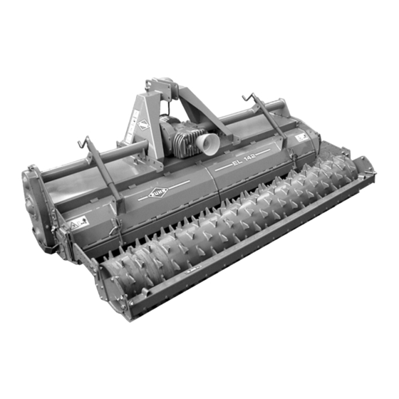
- Page 1 ASSEMBLY / OPERATOR'S MANUAL EL 142 POWER TILLER / CULTITILLER / CULTIPLOW No. 95461CGB A 08.2003...
- Page 2 DEAR OWNER, In buying a KUHN machine you have chosen wisely. Into it have gone years of thought, research and improvements. You will find, as have thousands of owners all over the world, that you have the best that engineering skill and actual field testing can produce. You have purchased a dependable machine, but only by proper care and operation can you expect to receive the performance and long service built into it.
-
Page 3: Table Of Contents
TABLE OF CONTENTS PAGE Safety Safety Decals - Model identification plate Technical Specifications Guards Fitting to the tractor PTO shaft Slip clutch Rotor speeds (rotational frequencies) Adjustment of the rear hood Equipment 1) Rollers 2) Skids + stand 3) Gauge wheel kit 4) Side separating discs 5) Rear wheel kit 6) Track eradicators... -
Page 4: Safety
- using only genuine spare parts, equipment and accessories as designated by the manufacturer. The EL 142 must only be operated, maintained and repaired by competent persons who are familiar with machine specifications and operations and are aware of any danger involved. - Page 5 GENERAL SAFETY RECOMMENDATIONS Before operating the machine, always ensure that tractor and machine are in accordance with work safety and road traffic regulations. BASIC PRINCIPLES 1. In addition to the recommendations given in this manual, legislation on work safety and accident prevention must also be respected.
- Page 6 17. Drive speed must be adapted to ground conditions as well as roads and paths. Always avoid abrupt changes of direction. 18. Precision steering, tractor adherence, road holding and efficient braking are influenced by the type of implement, weight, ballast of front axle, ground or road conditions. It is therefore of utmost importance to be cautious in every given situation.
- Page 7 POWER TAKE-OFF 1. Only use PTO shaft supplied with the machine or recommended by the manufacturer. 2. PTO guards must always be in place and in good condition. 3. Check for correct PTO overlap when at work and in transport. 4.
- Page 8 HYDRAULIC SYSTEM 1. WARNING ! Hydraulic system is under pressure. 2. When fitting hydraulic motors or cylinders, ensure that connections have been made correctly, as per manufacturer’s instructions. 3. Before connecting hoses to the tractor hydraulics, ensure that tractor and machine circuits are not under pressure.
- Page 9 8. Spare parts used must be in accordance with specifications and standards as defined by the manufacturer. Use only genuine KUHN parts ! 9. Before any electric welding is carried out on tractor or attached machine, disconnect generator and battery terminals.
-
Page 10: Safety Decals Model Identification Plate
SAFETY DECALS MODEL IDENTIFICATION PLATE The following safety pictorials have been placed on your machine in the areas indicated. They are intented for your personal safety and for the safety of the people working with you. The text shown on them gives their precise meaning. Keep the pictorials clean. Replace them when they are faded. - Page 11 - 9 -...
-
Page 12: Technical Specifications
TECHNICAL SPECIFICATIONS SPECIFICATIONS EL 142 EL 142 Working width m (ft) 2.50 (8’2") 3.00 (9’10") P.T.O. 750 rpm (min 77 (105) Maxi. allowable DIN power kW (hp) P.T.O. 1000 rpm (min 103 (140) Minimum power requirement kW (hp) 66 (90) - Page 13 SPECIFICATIONS EL 142 EL 142 Weight with packer roller : (kg / lbs) - POWER TILLER with standard diameter C-blade rotor 1400 (3080) 1560 (3432) - POWER TILLER with larger diameter L-blade rotor 1450 (3190) 1615 (3553) - CULTIPLOW rotor with 2 bolts per blade...
-
Page 14: Guards
GUARDS 1) Front safety guards The safety guards increase the safety of the machine. The 2 front safety guards (P) are made up of 3 parts, one fixed and 2 sliding sections. They are factory fitted as shown on photo 1. The sliding sections of the safety guards may need to be repositioned (front wheels, track eradicators…). -
Page 15: Fitting To The Tractor
FITTING TO THE TRACTOR The EL 142 can be fitted to all tractors equipped with a standard Cat. 2 or Cat. 3 three-point hitch (figure 7). Category "2" - original equipment Alternative attachment : Category “ 3 N ” (with a cat.2 space between lower lift arms) Recommended with a EL 142/seed drill combina- tion. -
Page 16: Pto Shaft
P.T.O. DRIVE SHAFT Make sure the EL 142 is resting on the ground and is maintained in a stable position. Clean and lubricate the gearbox input shaft and slide the mating PTO shaft yoke in place. Before attaching the PTO shaft to the slip clutch flange, it is essential that both mating surfaces are thoroughly cleaned. - Page 17 A hook (C) is supplied with the machine to support the PTO shaft (T) when disconnected to avoid damage or deterioration due to contact with the ground (photo 11). To avoid accidents which could be serious, make sure that the guards are always correctly in place and secured with the safety chains.
-
Page 18: Slip Clutch
FRICTION SLIP CLUTCH The EL 142 is factory equipped with an adjustable friction slip clutch. Spring pressure is factory pre-set (L = 32 mm / 1 1/4") for 103 kW (140 hp) tractors at 1000 rpm (min ) PTO (photo 12). -
Page 19: Rotor Speeds (Rotational Frequencies)
ROTOR SPEED (ROTATIONAL FREQUENCY) The EL 142 is fitted with a speed gearbox which adapt the rotor speed (rotational frequency) to the working conditions. To change the PTO speed (rotational frequency) invert or replace the sets of matching gearwheels located at the rear of the gearbox. - Page 20 The gearbox is factory fitted with a rear PTO shaft (S) which rotates at the same speed (rotational frequency) as the tractor PTO shaft (photo 16). An extra implement can be driven by a secondary PTO shaft which should be assembled and used according to the legislation in force at the time.
-
Page 21: Adjustment Of The Rear Hood
ADJUSTMENT OF THE REAR HOOD The rear hood unit consists of: - Hood (Q) the position of which can be adjusted by cranked handles (P) (photo 17) - Flap (R) which can be adjusted and locked by inserting pins (B) into holes (S) (photos 18 and 19) The desired tilth can be obtained by adjusting the position of rear hood (Q): - lowering the hood increases the working of the... -
Page 22: Use
CULTIPLOW version eliminates nearly all risks of clogging and building up of plant residues. The roller controls working depth and levels and packs the seedbed behind the machine. The EL 142 CULTITILLER or CULTIPLOW is a very versatile machine offering a wide range of appli- cations :... - Page 23 - Do not disengage the PTO drive unless the machine has been lifted out of work. Important remarks : Like many farm machines, use of the EL 142 entails limits which must be respected in all situations. These limits are often tied in with :...
-
Page 24: Equipment
- either a packer roller (studs welded onto a cylinder), - either a packer roller PK2 (studs welded onto a cylinder) (only for EL 142 - 3,00 m), - either a maxipacker roller (rows of discontinuous studs welded on a large diameter cylinder), - either a crumbler roller (welded tubes and removable bars) - or a maxicrumbler roller (welded tubes). - Page 25 - EL 142 - 2.50 m : Kit No.121 6650 (standard) - EL 142 - 3.00 m : Kit No.121 6600 (standard), Kit No. 121 7080 (PK2) This rollers are particularly intended for use in wet or sticky soils. Efficient packing, proper levelling and good crumbling are always achieved.
- Page 26 b) Adjusting scraper plates - Slightly loosen fixing bolts (V) of the scrapers (P) so that they slide freely (figure 24, page 23). - Check that their position is central relative to the rows of roller teeth. The scraper supports have elongated holes to allow readjustment if necessary.
- Page 27 Fit the 2 adjusters (Q) (photo 30). Using the 2 nuts (S) on the adjusters, bring the scraper bar towards the roller until it is almost bottomed-out in the 2 slots of the support arms (D) (photo 30). Then tighten the 6 bolts (R) to a torque of 22 daNm / 160 ft.lbs, and if required adjust the position of the scraper plates (P) as shown thereafter.
-
Page 28: Skids + Stand
2) SKIDS + STAND (photos 35 and 35 A) Kit no 120 9210 The EL 142 can be equipped with 2 skids which must be mounted on each side of the machine. This equipment is recommended in Cultirotor version when no roller for working depth control is fitted. -
Page 29: Gauge Wheel Kit
3) FRONT GAUGE WHEELS (photo 36) Kit no 121 6640 The EL 142 can be equipped with a gauge wheel kit. Wheels (R) are fitted on cross tube (T) in front of the machine. This equipment is recommended either in... -
Page 30: Side Separating Discs
4) SIDE SEPARATING DISCS (photos 38 and 38A) Kit no. 121 6630 These discs improve soil movement towards the rotor and thus achieve a better definition between worked and unworked land. The side separating discs also help to stabilize the machine during surface work. Fit the side separating discs (D) to the cross bar (T) as shown in photo 38. -
Page 31: Rear Wheel Kit
5) REAR WHEEL KIT (photos 39 and 40) Kit no. 121 6360 for EL 142 - 2.50 m Kit no. 121 6370 for EL 142 - 3.00 m Rear wheels can be fitted in place of the roller for certain surface operations (for example, stubble clearing or turning over pastures). -
Page 32: Track Eradicators
6) TRACK ERADICATORS In order to reduce the tractor wheel marks left on the seedbed, the EL 142 may be equipped with wheel track eradicators. Depending upon the working conditions and machine widths, various types of track eradicators may - Kit no. 121 6610 for the traction bolt overload mechanism be ordered : - Kit no. -
Page 33: Rear Hydraulic Lift Linkage
Assembly : The hydraulic lift linkage is fitted to the EL 142 by means of axle (Q) and pins (U) (photo 43). A spacer washer (Ø 20 x 45 x 8) must be added on each side of the headstock mounting plates in order to minimise the lateral play at (U). - Page 34 In order to reduce combination overhang as much as possible, the 3-point frame lower linkage hooks (A) can be adjusted horizontally through a range of 22 cm (8,5") (photo 43 on page 31). Depending upon application, the standard position (as set in factory) can be changed. The alternative positions can be achieved as follows : - towards the rear : by combining the two rear positions of linkage arm (W) with the four holes (F) of arm (G) (photo 43 on page 31)
- Page 35 Maintenance of the linkage Periodically grease the different pivot points equipped with 8 grease nipples. When parking the combined unit (EL 142 / seed drill, for example) make sure that the additional implement is lowered first. Always put cover in place if the rear P.T.O. shaft is not used.
-
Page 36: A-Frame Kit For Venta Al And Ti Integrated Seeder Attachment
8) ADAPTATION KIT FOR VENTA AL AND TI INTEGRATED SEEDER There are two kits for EL 142 - 3.00 m - Floating adapter : Kit no. 121 6730 - Fixed adapter : Kit no. 121 6750 For assembling and operating instructions see the VENTA AL and TI instructions booklets. -
Page 37: Nylon Cleaning Plates For Standard Packer Roller, Packer Roller Pk2 And Maxipacker Roller Scrapers
11) NYLON CLEANING PLATES FOR STANDARD PACKER ROLLER, PACKER ROLLER PK2 AND MAXIPACKER ROLLER SCRAPERS Part No. 525 702 00 for the standard packer roller and the packer roller PK2 Part no. 525 923 00 for the maxipacker roller These cleaning plates are made from a supple synthetic material which enables them to be slightly pre compressed against the roller for improved cleaning action. -
Page 38: Signalling Elements
14) SIGNALLING ELEMENTS Kit no. 120 8840 Install the signalling elements as described below : - Fix the 4 supports (A) and (B) on the 2 adapter plates (C), at the rear of the right side plate, and on the rear left plate using 4 bolts (S) (M 16 x 35) and nuts (M 16) (torque 16 daNm) (see photos 47 and 48). -
Page 39: Maintenance
MAINTENANCE BEFORE CARRYING OUT ANY OPERATION SUCH AS MAINTENANCE OR ADJUSTMENT ON THE MACHINE, STOP THE TRACTOR ENGINE, REMOVE IGNITION KEY AND WAIT FOR ROTATING PARTS TO STOP BEFORE LEAVING THE TRACTOR. 1) LUBRICATION . PTO Shaft (fig. 51) : Grease PTO shaft telescopic tubes (A), universal joint bearings (B) and guard tubes (C) : every 8 hours of use with SHELL Multi-Purpose grease NLGI... -
Page 40: Fitting Blades
2) FITTING THE BLADES a) POWER TILLER with standard diameter C- blade rotor (fig. 54 and photo 55) The blades can be fitted in two different ways, depending on the job to get done : - 3 pairs of blades per flange 3 right blades (D) and 3 left blades (G) (as fitted at factory) - 2 pairs of blades per flange 2 right blades (D) and 2 left blades (G) - Page 41 b) POWER TILLER with larger diameter L- blade rotor (fig. 56 and photo 57) The blades can be fitted in two different ways, depending on the job to get done : - 3 pairs of blades per flange 3 right blades (D) and 3 left blades (G) (as fitted at factory) - 2 pairs of blades per flange 2 right blades (D) and 2 left blades (G) NUMBER OF BLADES...
- Page 42 c) CULTITILLER rotor with Fast-Fit blades The CULTITILLER rotor is equipped with angled left and right blades, solidly housed in individual supports welded on the rotor tube (photos 58 and 58A). Start fitting blades on the support nearest the side gearbox.
-
Page 43: Changing The Rotor
e) CULTIPLOW rotor with 1 bolt per blade (photo 60) This CULTIPLOW rotor is fitted with left and right angled blades. To distinguish left blades from right blades, refer to part number marked on the back of each blade (K1631030 = left blade, K1631040 = right blade). -
Page 44: Trouble Shooting
TROUBLE SHOOTING PROBLEM CAUSE REMEDY Noisy drive when lifting Top link of 3-point hitch badly Position the top link parallel the machine positioned/adjusted to the lower lift arms (page 14) Excessive lifting height - Reduce lifting height - Should the problem persist, dis- engage the PTO shaft when lift- ing the machine. - Page 45 Vegetable residue build up Poor shredding and distribution Operate an independant shredder on seed drill coulters when of vegetable residue first using an EL 142 / seed Use a seed drill specially drill combination. equipped for seeding in vegetable residue. Ridging across...
- Page 46 PROBLEM CAUSE REMEDY Erratic packer roller Worn or incorrectly adjusted Position scraper plates closely function scraper plates to the roller (see pages 24 and 25) Rely on hard coated scraper plates or nylon cleaning plates in case of excessive wear (pages 34 and 35) Scrapers jammed by trash Clean the scrapers by pivoting them to the rear (pages 24 and 25)
-
Page 47: Conditions Of Limited Warranty
SOUND LEVELS Sound levels given out by : EL 142 Power Tiller / Cultitiller / Cultiplow Sound levels have been measured in accordance with the measuring methods as defined in: EN 1553 << Agricultural machinery - Agricultural self-propelled, mounted, semi-mounted and trailed machines - Common safety requirements >>... - Page 48 1. Normal maintenance such as greasing, maintenance of oil levels, minor adjustments, etc. 2. Transportation of any kind of any KUHN product to and from the place the warranty work is performed. 3. Dealer travel time to and from the machine or to deliver and return the machine from the workshop for repair.
- Page 49 Company and have no right or authority to assume any obligation on their behalf, express implied, or to bind them in any way. KUHN S.A. reserves the right to incorporate any change in design in its products without obligation to make such changes on units previously manufactured.
- Page 50 - N O T E S -...
- Page 51 This machine complies with the safety requirements of the European machinery directive. The Operator should respect all Health and Safety regulations as well as the Highway Code. For your own safety, use only genuine KUHN spare parts. The manufacturer disclaims all responsibilities due to incorrect use or non-compliance with the...
- Page 52 KUHN parts KUHN S.A. 4 Impasse des Fabriques F - 67706 SAVERNE CEDEX (FRANCE) Tél. : + 33 (0) 3 88 01 81 00 - Fax : + 33 (0) 3 88 01 81 03 www.kuhnsa.com - E-mail : info@kuhnsa.com...
Need help?
Do you have a question about the EL 142 and is the answer not in the manual?
Questions and answers