Table of Contents
Advertisement
Quick Links
Advertisement
Table of Contents

Subscribe to Our Youtube Channel
Related Manuals for Detcon MicroSafe DM-634C


Summary of Contents for Detcon MicroSafe DM-634C
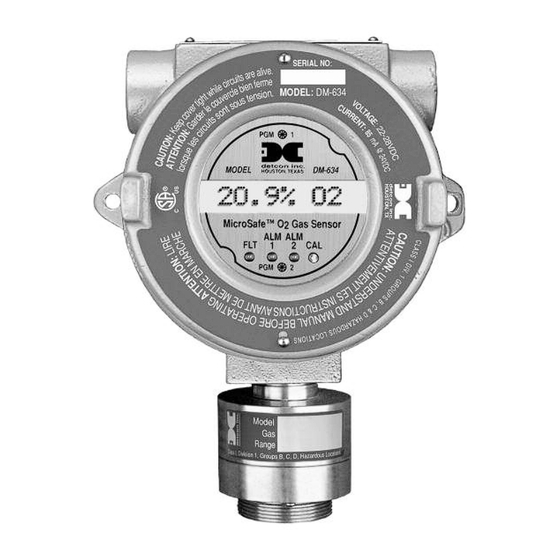
- Page 1 Detcon MicroSafe™ Model DM-634C Oxygen Deficiency Sensor (0-25% O2) Operator’s Installation and Instruction Manual DETCON, Inc. 4055 Technology Forest Blvd, Suite 100, The Woodlands, Texas 77381 Ph.281.367.4100 / Fax 281.298.2868 www.detcon.com August 03, 2018 • Document #2016 • Revision .066...
- Page 2 DM-634C Oxygen Sensor Assembly This page left intentionally blank DM-634C O2 Sensor Instruction Manual...
-
Page 3: Table Of Contents
DM-634C Oxygen Sensor Assembly Table of Contents Description ..............................1 3.0.1 Sensor Technology ........................1 3.0.2 Microprocessor Control Circuit ....................2 3.0.3 Base Connector Board ........................2 3.0.4 Explosion Proof Enclosure ......................3 Principle of Operation .......................... 3 Application ............................4 3.2.1 Sensor Placement/Mounting ...................... - Page 4 Table 1 Interference Data ..........................4 Table 2 Field wiring Table ..........................6 Shipping Address: 4055 technology Forest Blvd, Suite 100., The Woodlands Texas 77381 Mailing Address: P.O. Box 8067, The Woodlands Texas 77387-8067 www.detcon.com Phone: 888.367.4286, 281.367.4100 • Fax: 281.292.2860 • • sales@detcon.com...
-
Page 5: Description
DM-634C Oxygen Sensor Assembly Description Detcon MicroSafe™ Model DM-634, oxygen deficiency sensors are non-intrusive “Smart” sensors designed to detect and monitor O2 in air over the range of 0-25%. One of the primary features of the sensor is its method of automatic calibration which guides the user through each step via instructions displayed on the backlit LCD. -
Page 6: Microprocessor Control Circuit
DM-634C Oxygen Sensor Assembly 3.0.2 Microprocessor Control Circuit The control circuit is microprocessor based and is packaged as a plug-in field replaceable module, facilitating easy replacement and minimum down time. Circuit functions include a basic sensor pre-amplifier, on-board power supplies, microprocessor, back lit alpha numeric display, alarm status LED indicators, magnetic programming switches, an RS-485 communication port, and a linear 4-20 mA DC output. -
Page 7: Explosion Proof Enclosure
DM-634C Oxygen Sensor Assembly 3.0.4 Explosion Proof Enclosure The sensors are packaged in a cast metal explosion proof enclosure. The enclosure is fitted with a threaded cover that has a glass lens window. Magnetic program switches located behind the transmitter module face plate are activated through the lens window via a hand-held magnetic programming tool allowing non- intrusive operator interface with the sensor. -
Page 8: Application
DM-634C Oxygen Sensor Assembly Application Model DM-634 MicroSafe™ sensors are designed to detect and monitor oxygen deficiency in ambient air in the range of 0-25%. Minimum sensitivity and scale resolution is 0.1%. Operating temperature range is -4° F. to +122° F. While the sensor is capable of operating outside these temperatures, performance specifications are verified within the limit. -
Page 9: Operating Software
DM-634C Oxygen Sensor Assembly Operating Software Operating software is menu listed with operator interface via the two magnetic program switches located under the face plate. The two switches are referred to as “PGM 1” and “PGM 2”. The menu list consists of 3 items which include sub-menus as indicated below. -
Page 10: Alarm 1 Level Adjustment
3.5.1 Field Wiring Table (4-20 mA output) Detcon MicroSafe™ O2 sensor assemblies require three conductor connection between power supplies and host electronic controllers. Wiring designators are + (DC), – (DC), and mA (sensor signal). Maximum single conductor resistance between sensor and controller is 10 ohms. Maximum wire size for termination in the... -
Page 11: Sensor Location
DM-634C Oxygen Sensor Assembly 3.5.2 Sensor Location Selection of sensor location is critical to the overall safe performance of the product. Five factors play an important role in selection of sensor locations: (1) Density of the gas to be detected (2) Most probable leak sources within the industrial process (3) Ventilation or prevailing wind conditions (4) Personnel exposure... -
Page 12: Accessibility
DM-634C Oxygen Sensor Assembly 3.5.4 Accessibility Consideration should be given to easy access by maintenance personnel as well as the consequences of close proximity to contaminants that may foul the sensor prematurely. Conduit "T" EYS Seal Fitting MODEL DM-534C HOUSTON, TEXAS MicroSafe O2 Gas Sensor Drain... -
Page 13: Figure 7 Typical Outline And Mounting Dimensions
DM-634C Oxygen Sensor Assembly NOTE: If a voltage signal output is desired in place of the 4-20mA output, a 1/4 watt resistor must be installed in position R1 of the terminal board. A 250Ω resistor will provide a 1-5V output (– to mA). A 100Ω resistor will provide a .4-2V output, etc. This linear signal corresponds to 0-100% of scale (see Figure 8). -
Page 14: Figure 8 Sensor Connector Pcb
DM-634C Oxygen Sensor Assembly Alarm Dry Contacts Fault ALM2 ALM1 Optional Voltage Developing Resistor Use 250ohm 1/4W ALM1 VDC Power In Jumper Programmable Alarm Outputs ALM2 Normally Open or Normally Closed 4-20mA Output Fault RS-485 In Place un-used alarm RS-485 Out programming jumper tabs here TO SENSOR... -
Page 15: Figure 9 Control Circuit
DM-634C Oxygen Sensor Assembly CPU Board - Top View Alarm Programming Jumpers Latch CPU Board FAULT Energize Latch Ascending ALARM1 Energize Figure 9 Control Circuit If applicable, set the RS-485 ID number via the two rotary dip switches located on the pre-amp board (see Figure 10). - Page 16 DM-634C Oxygen Sensor Assembly ID# SW1 SW2 ID# SW1 SW2 ID# SW1 SW2 ID# SW1 SW2 ID# SW1 SW2 ID# SW1 SW2 none g) Replace the plug-in control circuit and replace the junction box cover. DM-634C O2 Sensor Instruction Manual Rev.
-
Page 17: Start Up
3.9.2. Initial operational tests are complete. Detcon O2 gas sensors are pre-calibrated prior to shipment and will, in most cases, not require significant adjustment on start up. However, it is recommended that a complete calibration test and adjustment be performed within 24 hours of installation. -
Page 18: Calibration Procedure - Span
DM-634C Oxygen Sensor Assembly NOTE: If, after entering the calibration or program menus, there is no interaction with the menu items for more than 30 seconds, the sensor will return to its normal operating condition. Figure 11 Magnetic Programming Tool 3.7.1 Calibration Procedure - Span NOTE 1: Before performing an ambient air O... -
Page 19: Additional Notes
DM-634C Oxygen Sensor Assembly Figure 12 Programming Locations d) From the programming menu scroll to the calibration level listing. The menu item appears as: “SET CAL LEVEL”. Enter the menu by holding the programming magnet stationary over “PGM 1” for 3 seconds until the display reads “CalGas @ ## %”, then withdraw the magnet. -
Page 20: Calibration Frequency
DM-634C Oxygen Sensor Assembly 3.7.3 Calibration Frequency In most applications, monthly to quarterly calibration intervals will assure reliable detection. However, industrial environments differ. Upon initial installation and commissioning, close frequency tests should be performed, weekly to monthly. Test results should be recorded and reviewed to determine a suitable calibration interval. -
Page 21: Programming Alarms
DM-634C Oxygen Sensor Assembly Programming Alarms 3.9.1 Alarm Levels Both alarm 1 and alarm 2 levels are factory set prior to shipment. Alarm 1 is set at 19.5%; alarm 2 at 17.5%. Both alarms can be set in 0.1% increments from 2.5% to 22.5%. The following procedure is used to change alarm set points: a) First, enter the programming menu by holding the programming magnet stationary over “PGM 2”... -
Page 22: Program Features
Other protocols are available. Contact the Detcon factory for specific protocol requirements. Communication is two wire, half duplex 485, 9600 baud, 8 data bits, 1 stop bit, no parity, with the sensor set up as a slave device. A master controller up to 4000 feet away can theoretically poll up to 256 different sensors. - Page 23 DM-634C Oxygen Sensor Assembly Register# High Byte Low Byte 40000 Sensor Life Gas type is one of the following: 01=CO, 02=H2S, 03=SO2, 04=H2, 05=HCN, 06=CL2, 07=NO2, 08=NO, 09=HCL, 10=NH3, 11=LEL, 12=O2 Register# High Byte Low Byte 40001 Detectable Range i.e. 100 for 0-100ppm, 50 for 0-50% LEL etc. Register# High Byte Low Byte...
-
Page 24: Display Contrast Adjust
3.12 Display Contrast Adjust Detcon MicroSafe™ sensors feature a 16 character backlit liquid crystal display. Like most LCD, character contrast can be affected by viewing angle and temperature. Temperature compensation circuitry included in the MicroSafe™ design will compensate for this characteristic, however temperature extremes may still cause a shift in the contrast. -
Page 25: Trouble Shooting
DM-634C Oxygen Sensor Assembly 3.13 Trouble Shooting Memory or Error Reports 1. Re-initialize Sensor - Unplug transmitter and re-plug transmitter then swipe magnet over PGM 1 in the first 3 seconds. This will clear the processor and recover from error state. Remember to put in all customer settings for range, alarm and cal gas level after re-initialization. -
Page 26: Spare Parts List
DM-634C Oxygen Sensor Assembly 3.14 Spare Parts List 613-120000-700 Sensor Splash Guard 943-000006-132 Threaded Calibration Adapter 500-001794-004 Connector Board 327-000000-000 Programming Magnet 897-850800-000 3-Port Enclosure less cover 897-850700-000 Enclosure glass lens cover 960-202200-000 Condensation Prevention Packet (replace annually) 370-399100-000 Plug-In replacement O2 sensor cell 926-345500-025 Plug-In control circuit Customer Supplied... -
Page 27: Warranty
Detcon, Inc., further provides for a five year fixed fee service policy wherein any failed transmitter shall be repaired or replaced as is deemed necessary by Detcon, Inc., for a fixed fee of $65.00. The fixed fee service policy shall affect any factory repair for the period following the two year warranty and shall end five years after expiration of the warranty. -
Page 28: Software Flowchart
DM-634C Oxygen Sensor Assembly 3.17 Software Flowchart LEGEND: AUTOSPAN PGM1 - Program Switch Location #1 PGM2 - Program Switch Location #2 PGM2 (3) (M) - Momentary pass of magnet CALIBRATION (3) - 3 second hold of magnet 2-SPAN (30) - 30 second of magnet inc - Increase PGM1 (3) PGM1 (M) -
Page 29: Revision Log
08/02/18 Updated Conduit Seal in Section 3.5.4 Shipping Address: 4055 technology Forest Blvd, Suite 100., The Woodlands Texas 77381 Mailing Address: P.O. Box 8067, The Woodlands Texas 77387-8067 www.detcon.com Phone: 888.367.4286, 281.367.4100 • Fax: 281.292.2860 • • sales@detcon.com DM-634C O2 Sensor Instruction Manual Rev.
Need help?
Do you have a question about the MicroSafe DM-634C and is the answer not in the manual?
Questions and answers