Table of Contents
Advertisement
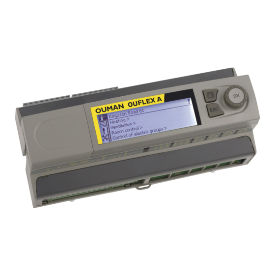
Freely programmable automation device
- Ouflex A is a DIN-rail-attachable, monitoring-, controlling- and regulating device.
- The DIN-standard-compatible structure of the Ouflex A device enables installation
to most common cabinets.
- Detachable strip connectors make installation easier.
KEY WORDS
Key words:
Active alarms
Alarm history
Use of a GSM phone requires that
the GSM modem (optional) is con-
nected to the controller.
OUFLEX
USER MANUAL
OUNET
Internet-based on-line control room
for professional remote
control and monitoring (optional).
EH-net
Local Web Server
remote control and monitoring (op-
tional).
Advertisement
Table of Contents

Subscribe to Our Youtube Channel
Related Manuals for OUMAN Ouflex A


Summary of Contents for OUMAN Ouflex A
- Page 1 OUFLEX Freely programmable automation device USER MANUAL - Ouflex A is a DIN-rail-attachable, monitoring-, controlling- and regulating device. - The DIN-standard-compatible structure of the Ouflex A device enables installation to most common cabinets. - Detachable strip connectors make installation easier.
- Page 2 Ouflex A is a DIN-rail-attachable and freely programmable device designed for monitoring, controlling and regulating. The device is programmed with Ouflex BA Tool utility and the prepared program is loaded to the Ouflex device via Ethernet connection. It is possible to increase the number of I/O-points with external I/O-mo- dules via Modbus RTU connections.
-
Page 3: Table Of Contents
3.3.2 Weekly schedule .............................. 16 3.3.3 Special days ..............................17 3.3.4 Exception schedule ............................17 4 Settings .................................18 5 Naming ..................................19 6 Communication via a mobile phone ........................19 7 Ouflex A device I/O connections and structure ....................20 Extension units ..............................22 Technical information ............................24... -
Page 4: System Settings
6. Enter Device ID (optional). Test the SMS communication. Send a message to Ouflex A: Keywords. If the controller replies with a message containing a list of key words, text message communication is ok. If the controller doesn’t send a text messa- ge, make power cut and turn it back. - Page 5 SIM card release button first! Insert SIM card into the slot and make sure it settles properly. Push the slot back to its place. Enter the SIM card PIN code in Ouflex A device. Make sure PIN inquiry is in SIM card release button use in the SIM card.
-
Page 6: Network Settings
Modbus RT U master (COM1 (RJ45 in the end of device)) > Connection status indicates whether Ouflex A device is in the network or not. Ouflex A device can be connected to a local network or the Internet. If you use a protected VPN connection using OUMAN Access service, the controller displays the network mode OUMAN Access. -
Page 7: Time Settings
Ouman system and activates the service based on the serial number of the Ouflex A device. After that, you have to activate the ACCESS service from the device. OUMAN ACCESS- device can be connected to LAN if following condi- tions are fulfilled: 1. - Page 8 System settings > Network settings -> Modbus TCP/IP Modbus TCP/IP settings Modbus TCP server settings are changed via Modbus TCP/IP settings. It is possible to communicate with an Ouflex A device and the Mod- Modbus TCP/IP bus/RTU slave devices connected to it via Modbus TCP/IP interface.
-
Page 9: Display Settings
System settings -> Network settings -> Modbus RTU slave (COM3 (A2/B2)) Modbus RTU slave (COM3 (A2/B2)) Ouflex A device can be connected to Modbus RTU bus as a master or a A2/ B2 slave device. Bus settings are configurable. Every device connected to Address 1 >... -
Page 10: Do Backup And Restore Factory Settings
1.7 Do backup and restore factory settings System settings -> Backup It is recommended to make a backup as soon as Ouflex A has been taken into use and property-specific settings have been made. You may also restore factory settings. -
Page 11: Alarms
2 Alarms In the alarm menu of Ouflex A device, you can check the active A l a r m s alarms and what alarms have been active. The number of active Active alarms > Alarm history > alarms will is shown in the right corner of the main view. - Page 12 If alarms are routed, alarm information is sent to the alarm team by text message. Alarms are relayed according to the alarm routing time schedule. You can acknowledge an alarm by sending the same message back to the Ouflex A.
- Page 13 2.6 Alarm receivers Alarms > Alarm receivers In Ouflex A, alarms are directed to alarm teams. A team may con- Alarm receivers tain up to 5 phone numbers and another team as a backup user. Team 1 > An alarm is directed to the team that has been defined as its alarm Team 2 >...
-
Page 14: Point Information
Time programs grams. > 3.1 Wiring info Point info -> Wiring info Point information shows all the inputs and outputs of the Ouflex A Wiring info INPUTS: device and display names. It also shows the measurement value or U1:UI 1 -10.3 °C >... -
Page 15: Time Programs
> moment. Control command can be either a weekly schedule or ex- ception schedule. Heating H1 Temperature drop When you press the ”Present value” line OK, Ouflex A device asks for a Present value Weekly schedule > service code. After entering the service code, you can change the cont- Exception schedule >... -
Page 16: Weekly Schedule
3.3.2 Weekly schedule Point info -> Time programs -> Weekly schedule Graph Weekly programs have a general graphic view and an editing view, Weekly/24-hour program where you can see when the control is activated. (e.g., temperature Monday > drop, car heating on, lights on). Tuesday >... -
Page 17: Special Days
3.3.3 Special days Point info -> Time program > Special days You can enter special day programs as exceptions to normal week- ly programs. You can designate a maximum of 7 special day po- Graph Relay 3 Special days grams (SD). A special day program is typically created for each SD 1 >... -
Page 18: Settings
You can lock the settings in Ouflex A device system settings. If a GSM modem is connected to Ouflex A device and the setting values have been brought into SMS interface, you can ed- it settings by text message. Send a message “Key words”. The reply message shows you which key words are in use in the application. -
Page 19: Naming
/. You can write the key word using capital or small letters. Write only one key word/message. Store the key words into your phone’s memory. Informative messages can not be edited or sent back to the Ouflex A. Informative messages Informative messages are, for example. -
Page 20: Ouflex A Device I/O Connections And Structure
7 Ouflex A device I/O connections and structure Ouflex A is a freely programmable and DIN-rail-attachable building automation system for control and monitoring. The DIN-standard-compatible structure of the Ouflex A device enab- les installation to most common cabinets. Detachable strip connectors make installation easier. - Page 21 Ouflex A includes 34 I/O-points, and also versatile data transfer and field bus connections. In additi- on, the device contains 24 Vac and 15 Vdc outputs. Display unit is detachable, and can be relocated. It is possible to increase the number of I/O-points with external I/O-modules via bus connections.
-
Page 22: Extension Units
Extension units Extension units FLEX UI8 FLEX UI8 device has 8 universal inputs. 59 mm Supported signals and sensor types are: • transmitters 0-10V • transmitters 0/4-20mA • digital contact input • potential free pulse counter 91 mm 71 mm •... - Page 23 Interface card for modem and local I/O extension - unisolated RS-485 bus, supported protocols Modbus-RTU - USB host connection (not in use) - 15 Vdc voltage output, max 750 mA (total capacity together with the Ouflex A device 15 Vdc voltage output (strip connector 93)
-
Page 24: Technical Information
RS-485 bus (A1 and B1) Galvanically isolated, supported protocols Modbus-RTU RS-485 bus (A2 and B2) Galvanically isolated, supported protocols Modbus-RTU USB-host connection RS-232-modem, Ouman GSM-modeemi USB-device connection Ethernet Full-duplex 10/100 Mbit/s, supported protocols Modbus-TCP/IP Ouman Access Intelligent remote connection built-in for use with Ounet and Ouflex BA Tool...
Need help?
Do you have a question about the Ouflex A and is the answer not in the manual?
Questions and answers