
Related Manuals for Victor iCNC XT


Summary of Contents for Victor iCNC XT
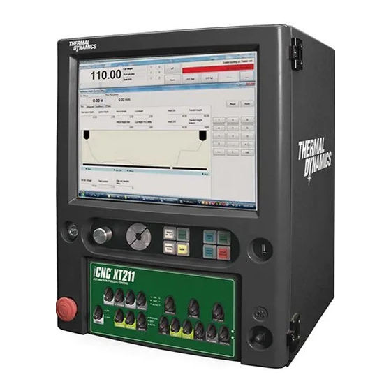
- Page 1 XT™ CNC CONTROLLER Operating Manual Revision: AA Issue Date: January 16, 2014 Manual No.: 0-5299 VictorThermalDynamics.com...
- Page 2 WE APPRECIATE YOUR BUSINESS! Congratulations on your new Victor Thermal Dynamics product. We are proud to have you as our customer and will strive to provide you with the best service and reliability in the industry. This product is backed by our extensive warranty and world-wide service network. To locate your nearest distributor or service agency call 1-800-426-1888, or visit us on the web at www.thermal-...
- Page 3 While the information contained in this Manual represents the Manufacturer's best judgement, the Manufacturer assumes no liability for its use. CNC Controller ™ Operating Manual No. 0-5299 Published by: Victor Technologies 82 Benning Street West Lebanon, New Hampshire, USA 03784 (603) 298-5711 www.thermal-dynamics.com © Copyright 2013 by Victor Technologies All rights reserved.
- Page 4 TABLE OF CONTENTS...
-
Page 5: Table Of Contents
TABLE OF CONTENTS SECTION 1: SAFETY INFORMATION ................1-1 Notes, Cautions and Warnings ................ 1-1 Important Safety Precautions ................. 1-1 Publications ....................1-2 Note, Attention et Avertissement ..............1-3 Precautions De Securite Importantes ............. 1-3 Documents De Reference ................1-4 Declaration of Conformity North America ............ - Page 6 SECTION 5: OPERATION ................... 5-1 Cut Process Screen ..................5-1 Overview Main Screen ..................5-3 iCNC XT Operating Control Panel ..............5-6 Switch Descriptions and Functions ............... 5-10 XT2 Switch Description and Function ............5-12 XT242 Switch Description and Function ............5-13 XT211/231 Switch Description and Functions ..........
-
Page 7: Safety Information
XT SECTION 1: SAFETY INFORMATION GASES AND FUMES Gases and fumes produced during the plasma cutting process can be dangerous and hazardous to your health. Notes, Cautions and Warnings Throughout this manual, notes, cautions, and warnings are used to head out of the welding fume plume. -
Page 8: Publications
XT * These values apply where the actual arc is clearly seen. Experience has shown that lighter filters may be used when the arc is hidden by the workpiece. FIRE AND EXPLOSION Fire and explosion can be caused by hot slag, sparks, or the plasma arc. -
Page 9: Note, Attention Et Avertissement
XT 11. CGA Pamphlet P-1, SAFE HANDLING OF COMPRESSED Coupant à l’arc au jet de plasma produit de l’énergie GASES IN CYLINDERS, obtainable from the Compressed électrique haute tension et des émissions magnétique Gas Association, 1235 Jefferson Davis Highway, Suite 501, qui peuvent interférer la fonction propre d’un “pace-... -
Page 10: Documents De Reference
XT pour protéger votre peau contre les étincelles et les rayons de l’arc. CHOC ELECTRIQUE Remplacez toute lentille sale ou comportant fissure ou rognure. Les chocs électriques peuvent blesser ou même tuer. Le procédé au jet de plasma requiert et produit de l’énergie électrique haute tension. - Page 11 XT 3. NIOSH, LA SÉCURITÉ ET LA SANTÉ LORS DES OPÉRATIONS DE 10. Norme 51B de la NFPA, LES PROCÉDÉS DE COUPE ET DE SOUD- COUPE ET DE SOUDAGE À L’ARC ET AU GAZ, disponible auprès du AGE, disponible auprès de la National Fire Protection Association, Superintendent of Documents, U.S.
-
Page 12: Declaration Of Conformity North America
Rigorous testing is incorporated into the manufacturing process to ensure the manufactured product meets or exceeds all design specifications. Victor Technologies. has been manufacturing products for more than 30 years, and will continue to achieve excellence in our area of manufacture. -
Page 13: Declaration Of Conformity Europe/Ce
Rigorous testing is incorporated into the manufacturing process to ensure the manufactured product meets or exceeds all design specifications. Victor Technologies. has been manufacturing products for more than 30 years, and will continue to achieve excellence in our area of manufacture. - Page 15 XT Classification: The equipment described in this manual is Class A and intended for industrial use. WARNING This Class A equipment is not intended for use in residential locations where the electrical power is provided by the public low- voltage supply system.
-
Page 16: Statement Of Warranty
1.10 Statement of Warranty ® LIMITED WARRANTY: Victor Thermal Dynamics Corporation (hereinafter “Thermal”) warrants that its products will be free of defects in workmanship or material. Should any failure to conform to this warranty appear within the time period applicable to the Thermal products option, of any components or parts of the product determined by Thermal to be defective. -
Page 17: Section 2: Specifications
10A slow blow fuse Optional IO Expander Card with 16 relay outputs available for all iCNC XT models (down draft control) On XT2 and XT242 all voltage outputs share the same inlet voltage level. There is no inlet for external voltage supply. If internal inlet cable is removed, external voltage for relay outputs can be connected to line &... -
Page 18: Mechanical Dimensions Xt Cnc
XT WARNINGS DO NOT CONNECT the controller directly to a computer through the RJ45 or RS232 port! Connections must be made with fiber optic devices, wireless LAN, short haul modems or other approved devices which provide galvanic isolation, due to ground loops, electrical noise, or high frequency which can destroy electrical components in the controller or host computer. -
Page 19: Power Requirements
The power connector is located at the backside of the CNC unit. The connector is a standard IEC C14 power connector. Use a IEC C13 plug to connect the main power to iCNC XT. The power requirement is shown in the product label at the lower left corner in the backside of the CNC. -
Page 20: Mechanical Dimensions Neugart Gearboxes
XT Mechanical dimensions Neugart Gearboxes SPECIFICATIONS Manual 0-5299... -
Page 22: Section 3: Installation
XT Cable routing suggestion The idea is to put the plasma torch, work, electrode, ohmic grounds etc cables to the opposite side from the I/O, encoder and motor cables (empty space shown in the picture). Use the gas hoses as a separator between the 2 cable sets. -
Page 23: Main Power
XT Main Power Use a IEC C13 plug to connect the main power to iCNC XT. The main power connector is shown in Section 2.5 Power requirements. Limit Switches Wiring Connect your normally closed limit switches in series as shown in the picture to connector J16 Limits. Y2 alignment switch is used to align the bridge when homing (optional feature). - Page 24 XT E-STOP POLARITY Name Default Remarks External E-STOP (remotely located) switch polarity, jumper vertically External E-STOP (remotely located) switch polarity, jumper vertically *NC = Normally Closed switch *NO = Normally Open switch. EXT E-STOP Name Default Remarks External E-STOP (remotely located) Circuit Bypass . (No external E-Stop push button installed)
-
Page 25: Yaskawa Motor And Servo Installation
XT Yaskawa Motor and Servo Installation The CNC may have a different combination of servo amplifiers. The Yaskawa amplifiers come either as 400W, 750W or a combination of both. Wiring them is almost the same, the only difference is that the 750W drives has a bigger diameter motor cable so please ensure that the bigger wattage amplifiers get the thicker cable. - Page 26 XT Routing the cables in the cable track Start by routing and connecting the cables to the motors, both encoder and motor cable. Try to route the motor and encoder cables on the opposite side from the possible plasma torch, work and electrode cables in the cable track. Mark the cable ends that go to the cnc so you know into what servo amplifier you connect them inside the XT cnc.
- Page 27 XT 8. Put the grounding clip around the cable shield and screw it back to the amplifier. Add the motor cable ground wire (green/yellow) to the screw terminal next to the grounding clip. 9. Connect the encoder cable 10. Pull excess cable from the inside of the XT CNC and compile the cable gland. Put the cable gland seal to the cable gland.
-
Page 28: Down Draft And Laser Pointer Wiring (Xt 211 & 231 Only) Optional
XT Down Draft and Laser Pointer Wiring (XT 211 & 231 ONLY) OPTIONAL You can control the fume extraction manually or by automatic. The switch marked Table controls the output on J30 pins #26 & #27. Connect your fume extraction motor ON/OFF relay to these pins, max contact current is 1A. -
Page 29: Plasma Communication, Plasma I/O
XT Plasma Communication, Plasma I/O 1. Connect the CNC end of the 9pin D connector to the serial port marked COM1 at the back of the XT CNC. 2. Connect the 37 pin male amp connector at the back of the XT CNC as follows: For XT211/XT231, J30 to the J30 plasma connector. For XT2/242, J25 to the J25 plasma connector. -
Page 30: Height Control,Communication And I/O Cables
XT Height Control,Communication and I/O Cables 1. Connect the plasma end of the communication cable to the plasma power supply connector J54 TCS /COMM 2. Connect the plasma end of the Plasma I/O Cable to the plasma power supply connector J15 CNC 3. -
Page 31: Voltage Divider For Ihc Torch Height Control
XT Voltage Divider for iHC Torch Height Control There is a space for mounting the V-D Board located on the upper portion of an internal vertical panel near the rear of the power supply. Pre- drilled holes for mounting the iHT V-D board as well as another popular height control are provided. -
Page 32: Oxy Fuel Installation
XT 3.10 Oxy Fuel Installation WARNINGS DO NOT CONNECT the main power before all wiring is done and all cables are connected from both ends. Always follow national wiring standard for wire sizes. This section provides a basic wiring guide for oxy fuel lifter, solenoids and capacitive sensor.. - Page 33 XT Main gas connector XT231 ONLY With the XT231 you can have separate outputs for each torch station and then select your active station with the Sel 1, Sel 2, Sel 3 switches on the switch panel. You also have a main gas connector, the station select switches are ignored in these outputs.
- Page 34 XT XT211 Position Default Remarks Inlet line voltage User VCC Position Default Remarks Inlet neutral voltage User GND 3-14 INSTALLATION Manual 0-5299...
- Page 35 XT XT231 JP10 Position Default Remarks Inlet line voltage User VCC JP11 Position Default Remarks Inlet neutral voltage User GND JP12/JP13/JP14 Position Default Remarks Inlet voltage lifter User AC voltage lifter Manual 0-5299 INSTALLATION 3-15...
-
Page 36: Oxy Fuel Lifter Wiring Ac
XT 3.11 Oxy Fuel Lifter Wiring AC By default the output connector will provide inlet voltage outputs. See previous page for voltage selection jumpers.. 3.12 Oxy Fuel Lifter Wiring DC You can provide your own DC voltage to pins #2 and #8. The relay logic will then swap the polarity of the voltage going into the lifter motor. If the lifter moves up when you press down from the switch and vice versa, just swap the wires in pins #4 and #6. -
Page 37: Oxy Fuel Capacitive Sensor Wiring
XT 3.13 Oxy Fuel Capacitive Sensor Wiring The above picture describes a common wiring for a capacitive sensor with a motor controller. Depending on the polarity to enable automatic height sensing use either pin#35 normally closed or pin #36 normally open. The example is for 24VDC inputs. -
Page 38: Setting Up The Motion
XT 3.14 Setting up the Motion CAUTION Disengage all motors from rails before doing the motion test. Disregarding this may result in mechanical damage. NOTE Important - Please complete all motion set up, in sequence, before operating the controller. -
Page 39: Unlocking The Hard Drive
XT 3.15 Unlocking the Hard Drive NOTE The system will reboot during the locking and unlocking of the Hard Drive. 1. Select Option 8. NOTE - the button will indicate the current Hard Drive status. Manual 0-5299 INSTALLATION 3-19... -
Page 40: Drive Configuration
XT 3.16 Drive Configuration Select 1. Motion --> 1.1. Drive Configuration: choose 2 or 3 axis depending on your machine. NOTE You must go through each of the 8 steps in the right column, 1.1, 1.2, 1.3 etc. through 1.8.. -
Page 41: Motor And Encoder Polarities
XT 3.17 Motor and Encoder Polarities NOTE Make sure the Drive Enable Switch on the front of the controller is “OFF” Make sure that the controller is in basic status (no lights-on in any of the 10 push buttons in front panel.) CAUTION Disengage all motors from rails before doing the motion test. -
Page 42: Encoder Values
XT 3.18 Encoder Values Select 1.3. Encoder Values from iCNC Setup. Normal encoder values are in the 100 000 – 5 000 000 range. You can calculate the encoder value like follows: Metric: (1005.3088mm x encoder pulses per revolution x 4 x gear ratio) / (module x π x number of teeth in pinion) = Encoder value Imperial: (39,57909 x encoder pulses per revolution x 4 x gear ratio) / (Effective Diameter x π) = Encoder value... - Page 47 XT 4. Double click Speed reference input gain. 6. Click Write. 7. Check your new maximum speed from the iCNC setup Max speed adjustment page. 8. Repeat procedure to further fine tune your maximum speed. Repeat steps to all axes so each one has the same max speed.
-
Page 50: Setting Motion Parameters
XT 3.23 Setting Motion Parameters The next step is 1.8. set motion parameters. Leave all parameters at default settings with the exception of the following: Set to 1.5 times the parking speed. Must be higher than maximum drift mm/min. -
Page 51: Setting Correct Inertia Ratio
0.00035 x 200kg x 45 ² = 141.75 Inertia ratio = 142% Round up the calculated value to the next even one. NOTE If you are unsure about your inertia ratio, please contact Victor Technologies technical support for assistance. Manual 0-5299 INSTALLATION 3-31... - Page 52 XT Click Edit. Type in your inertia ratio value and click Ok. Example a result of 65 = 65%, 125 = 125%. Disconnect from the drive and repeat steps for Y2 axis. Verify all changes have been completed at this point before going to the next step of locking the hard drive.
-
Page 53: Locking The Hard Drive
XT 3.25 Locking the Hard Drive CAUTION After the CNC installation is completed, the Hard Drive should be locked to protect the system against unintentional changes, viruses and corruption of files. It is highly recommended to run the system with the Hard Drive locked. - Page 54 XT This Page Intentionally Blank 3-34 INSTALLATION Manual 0-5299...
-
Page 55: Section 4: Quick Start And Operation
XT SECTION 4: QUICK START AND OPERATION WARNINGS DO NOT CONNECT the controller directly to a computer through the RJ45 or RS232 port! Connections must be made with fiber optic devices, wireless LAN, short haul modems or other approved devices which provide galvanic isolation, due to ground loops, electrical noise, or high frequency which can destroy electrical components in the controller or host computer. - Page 56 XT 3. Select the desired Cut Process based on the Process, Thickness, Gasses and Consumables in use. Click the desired process so it highlights in green. 4. Click Apply. 5. Click Close 6. Click Shapes 7. Select your macro, set the dimensions and click Ok.
- Page 57 XT 8. Click Send to cutting 9. Verify your process is correct and click Ok. 10. Drive your machine to the reference 0.0 position and zero your position. See 4.3.2 for Jog and Zero. 11. Click iHC Manual 0-5299...
- Page 58 XT 12. Click find plate and when done click minimize. 13. Click program start. See section 4.3 Note: See Promotion Nest and Plasma software manuals for more details. OPERATION Manual 0-5299...
-
Page 59: Section 5: Operation
XT SECTION 5: OPERATION Cut Process Screen Defi nition of areas under the Cut Process Tab shown on the XT CNC Thermal Screen 1. Use the drop down boxes to select the material and thickness to be cut. 2. The available cut processes for the selected material and thickness will be displayed along with information indicating which process is “B”... - Page 60 XT Other Tabs 1. CNC & THC tab shows the recommended default parameters the CNC will use for cutting as well as the recommended default param- eters the Torch Height Control will use during cutting for the process selected.
-
Page 61: Overview Main Screen
XT Overview Main Screen The main screen is divided into three parts. • Info (Systems Status) • Promotion Cut – Next Job Preview • Current Job 5.2.1 Info (System Status) Th is is located on top of the screen. The info screen shows system information and is used for diagnostics and troubleshooting. - Page 62 XT 5 .2.2 ProMotion Cut – Next Job Located on the left hand side of the screen, the Promotion Cut Screen is the starting point to navigate throughout the different screens. Opens the process selection window. Selecting the Shapes button will automatically open the Macro Shape Library in ProMotion Nest.
- Page 63 XT 5.2.3 C urrent Job Located on the right hand side of the screen, the Current Job window displays the current job being cut with real time tracking. Normally grayed out. Activated when a cutting program is stopped by pressing the Torch On/Off or the Stop–Backup but ton located on the front panel of the controller.
-
Page 64: Icnc Xt Operating Control Panel
• Reload saved job – Brings back the suspended saved program from the temporary fi le iCNC XT O perating Control Panel The iCNC® XT’s operating control panel is located below the LCD graphics screen. Most machine motion and cutting functions are initiated using this operating control panel. - Page 65 XT 5.3.3 Manual Mode Button Pressing the MANUAL MODE button activates the capability to jog and reposition the machine. CAUTION Pressing the MANUAL MODE button again will turn off the manual mode and will return the machine to the last know parked position.
- Page 66 XT 5.3.6 Torch ON/OFF B utton Pressing the TORCH ON / OFF button when manual mode is activated, will either manually start or turn off the cutting process. Note: When the start button is activated, and the cutting sequence is initiated, the TORCH ON/OFF button will automatically illuminate indicating the torch is on and the cutting sequence has started.
- Page 67 XT 5.3.9 Move Ahead Button The MOVE AHEAD button is illuminated whenever a program is running. Pressing the Torch On/Off button will stop the machine and the Move Ahead button will turn off. At this point, pressing the MOVE AHEAD button will cause the machine to move forward on programmed path without cutting.
-
Page 68: Switch Descriptions And Functions
XT Switch Descriptions and Functions 5.4.1 Emergency Stop - Button The Emergency Stop – Off button is used to remove power from the entire system in case of an emergency. It supplies power to the servos and cutting controls. The power to the CNC is not removed. Motion and cutting will stop immediately when the Emergency stop is pushed in. - Page 69 XT 5.4.2 Input Power Switch The Input Power Switch is a momentary switch. Toggling the switch up and holding for two seconds will turn on power to the CNC and the system. The proper way to switch power off is using Windows shutdown. This will switch off all power in the controller.
-
Page 70: Xt2 Switch Description And Function
XT XT2 Switch Description and Function 5.5.1 XT2 Switches and Descriptions Floating Head Switch • ON position will activate the Floating Head Output. • AUTO position allows the plasma cutting signal from a program to run the plasma. • OFF position will prevent activating the Floating Head. -
Page 71: Xt242 Switch Description And Function
XT XT242 Switch Description and Function 5.6.1 Station Select Switches Station Select Switches 1 – 4, Plasma 1 and Plasma 2 With the STATION SELECT switches the operator can select which torches are in use. • The fi rst 4 are Oxy-Fuel torches •... - Page 72 XT 5.6.2 Up / Down Switches All Up / Down switch (See upper box on the picture above) All Up / Down switch drives all the selected stations up and down. Individual Up / Down switches (See lower box on the picture above) Individual Up / Down switches will drive the corresponding station up or down, if the station is selected.
- Page 73 XT 5.6.4 High Preheat On/Off/Auto Switch This switch handles the Oxy Fuel High Preheat gases. • ON position will open the Hi Preheat solenoid valve. • Switch the gases OFF by moving this switch to the OFF position. • AUTO position will allow the cutting program to open the High Preheat solenoid when necessary.
- Page 74 XT 5.6.6 Marker On/Off/Auto Switch • ON position will activate the marker. This is used for testing. • AUTO position will be used when a cutting program includes marking. • OFF position will prevent activating the marker from a cutting program.
- Page 75 XT 5.6.8 Ignition Switch Pressing the ignition switch will activate the igniters (if installed). 5.6.9 Marker Down On/Auto Switch • ON position will activate the marker down signal. This is only used for testing. Important note: This switch in the ON position will cause the plasma start command to start the Marker instead of the plasma.
- Page 76 XT 5.6.10 IHS On/Off/Auto Switch This is a 3 position switch controlling either the IHS or the Floating head, depending on machine options. INITIAL HEIGHT SENSING SYSTEM • In Manual position the system activates the IHS output relay. • In Auto position the iCNC® XT activates the IHS output relay automatically •...
-
Page 77: Xt211/231 Switch Description And Functions
XT XT211/231 Switch Description and Functions 5.7.1 Station Select Switches NOTE: Switches Not available in XT211 (See blue box on the picture above) Station Select Switches 1 – 3. With the STATION SELECT switches the operator can select which Oxy Fuel torches are in use. - Page 78 XT 5.7.2 Up / Down Switches All Up / Down switch, (See bottom right most box “OXYFUEL”on the picture above) The All Up / Down switch, drives all the selected stations up and down. NOTE: Switches Not available in XT211 (See yellow box on the picture above) Individual Up / Down switches (See “PLASMA”...
- Page 79 XT 5.7.4 High Preheat On/Off/Auto Switch This switch handles the Oxy Fuel High Preheat gases. • ON position will open the Hi Preheat solenoid valve. • Switch the gases OFF by moving this switch to the OFF position. • AUTO position will allow the cutting program to open the High Preheat solenoid when necessary.
- Page 80 XT 5.7.6 Pointer On/Off Switch • ON position will activate the pointer device. • OFF position will turn off the pointer device 5.7.7 P.Power On/Off Switch • ON position will turn on the plasma power supply. • OFF position will turn off the plasma power supply.
- Page 81 XT 5.7.8 Table On/Off/Auto Switch • ON position will activate the table down draft • AUTO position will activate the table down draft when a cutting program is active • OFF position will turn off the table down draft.
- Page 82 XT 5.7.10 Marker On/Off/Auto Switch • ON position will activate the marker. This is used for testing. • AUTO position will be used when a cutting program includes marking. • OFF position will prevent activating the marker from a cutting program.
- Page 83 XT 5.7.12 Water Switch • ON position will activate the water spray signal. • AUTO position will allow the cutting program to command the water spray signal. • OFF position will prevent activating the water spray from a cutting program.
- Page 84 XT 5.7.14 Aux1 Switch • ON position will activate the aux1 signal. • AUTO position will allow the cutting program to command the aux1 signal. • OFF position will prevent activating the aux1 from a cutting program. 5.7.15 Aux2 Switch •...
-
Page 85: Starting Procedure
XT 5.7.16 Auto Switch • ON position will activate the auto signal, normally used for capacitive height sensing. • AUTO position will allow the cutting program to command the auto signal. • OFF position will prevent activating the auto from a cutting program. -
Page 86: Homing Procedure
XT Homing Procedure During initial power up, the iCNC® XT may display a Start homing procedure dialog box. If you select Yes, the machine will automatically locate the absolute zero home location. As a default, this is normally set at the bottom left corner of the cutting table, however this is selectable in the set-up parameters. -
Page 87: Jog
XT 5.10 Jog When selecting the Jog Button, the Jog dialog box will appear. You can use the Jog tool only when a cutting program is not running and the controller is not in Manual Mode. Use this tool to drive the machine to a position (X,Y) or to drive a distance (X,Y) from the current position. -
Page 88: Parameter Quick View
XT 5.11 Parameter Quick View The parameter quick view screen opens automatically when a program is sent to cutting from Promotion Nest or when the Setup button is clicked. The quick view screen allows the operator to change the most commonly used variable parameters quickly. It also provides options for plate alignment and advanced set up. -
Page 89: How To Proceed When Something Happens
XT 5.12 How To Proceed When Something Happens 5.12.1 How to Cancel a Cutting Program 1. Stop the machine movement and cutting by pressing TORCH ON/OFF or STOP BACKUP button. 2. Use the left mouse button to click the CANCEL PROGRAM button located at the top of the current job screen. - Page 90 XT 5.12.4 Manual Cutting 1. Press and release the MANUAL MODE button. 2. Drive the machine to the wanted piercing point by using the jog buttons. 3. Press and release TORCH ON/OFF button to start the cutting cycle. 4. Press the jog buttons of the desired direction to start the movement.
- Page 91 XT 5.12.7 Other Way to Check the Cutting Area You can check if the next cutting program fi ts on the plate this way as well. 1. Bring the cutting program to CURRENT JOB window by clicking the Next Job Preview button in it.
-
Page 92: Advanced Setup
XT 5.13 Advanced Setup The Advanced Setup screen allows the operator the fl exibility to change more parameters if needed. Advanced Setup has several folder tabs each containing different settings. You can change the tab by clicking it’s title. You can also build a material database of common materials being cut, and save different speeds and kerf values within each profi... - Page 93 XT 5.13.1. Parameters On the 1 Parameters tab the parameter quick view settings are shown again, along with creep speed, mirror and tool location. In addition a cutting process database can be set up by selecting material, thickness and tool.
- Page 94 XT Note: It is not necessary to use all three fi elds to set the database e.g. use material and thickness only and leave tool at Default. Setting up the Database A. Click inside the Add/Remove box to activate the “New” box and allow editing. Click New for Material and a new material dialog box opens.
- Page 95 XT 5.13.3. Line Marking Marking speed This is the speed selection for the marking tool. Tool location (X and Y) This is the marker location measured from the torch or laser pointer. SD1 and SD2 These delays are typically not used, but are fully available and programmable.
- Page 96 XT 5.13.4. Point Marking Tool location (X and Y) This is the marker location measured from the torch or laser pointer. This delay is typically not used but is fully available and programmable. Typically used for a marker down delay. This is the time that it takes for the marker to descend to marking height.
- Page 97 XT 5.13.5. Cutting Parameters Cutting speed This is the machine cutting speed. This setting duplicates the cutting speed setting in folder 1 Parameters. Changing one, changes the other. Rapid speed The machine speed during a non-cutting or rapid traverse move.
- Page 98 XT 1. START: Select the start delay at which the timing is to begin execution, eg. SD4. 2. PIERCING UP: Enter the desired time to raise the torch for piercing. 3. STAY UP: Enter the desired time to stay up before the pierce lowering time begins.
-
Page 100: Appendix
XT A.2.3 Lifter Mounting Base 4.48 in. (114 mm) 4 in. Stroke 12.45 in. (316 mm) 8 in. Stroke 3.5 in. 16.45 in. (89 mm) (418 mm) 1.5 in. (38 mm) Height: 316/418mm [12.44/16.47in] Width: 127mm [5.00in] Depth: 100mm [3.93in] with 89mm spacing in accordance to the hole center line. -
Page 101: Ihc User Interface
XT iHC User Interface The iHC can be almost invisible to the operator while the Height Control Parameters can come from the cutting program or fully automatically from the Material/Thickness/Tool parameter sets. Because this window does not hide any controls normally used to run the iCNC system it can be viewed at all times. - Page 102 XT when the AVC is active. APPENDIX Manual 0-5299...
-
Page 103: Main Settings
XT Main Settings This screen of pierce). Most of the parameters of the iHC can be directed in the Setup window. The upper and rightmost part of the Setup-window consist of buttons and fields which are always displayed. The lower left part of the Setup consists of several tabs. -
Page 104: System Setup & Diagnostic Menus
XT System Setup & Diagnostic Menus Advanced Tab Provides the option for more detailed control of the system behavior. Default Values Imperial Metric High Jog Speed 59,06 IPM 1500 mm/min Low Jog Speed 11,81 IPM 300 mm/min Adjust Speed... -
Page 105: I/O Bits Tab
XT plate. This feature can be used together with ohmic plate contact as a backup for the ohmic contact, or it can be used as primary plate sensing feature: ie cutting under water sensing more inaccurate (in case ohmic sensing is not active) force is disabled. -
Page 106: Service Tab
XT Lifter 1 Input Bits 9. IHS Start - Inbit from CNC becomes active when the IHS sequence starts. 10. Plate Contact - Inbit becomes active on plate contact during IHS or cutting sequence. 11. Main Arc - Inbit from plasma which indicates plasma arc has ignited. -
Page 107: Installation Tab
XT Installation Tab These parameters are password protected. Some parameters are the same as on the Advanced Tab. adding the Upper Soft Limit Distance to the position of the limit switch. tracting the Lower Soft Limit Distance from the position of the limit switch. Lower soft limit is supposed to be determined so that short motion below table surface is allowed but limiting the lifter from hitting the hard stop of the lifter. -
Page 108: Parameter Limits
XT A.10 Parameter Limits Parameter name Default Adjust speed 3000mm/min 18000 Collision recovery delay Collision retract height Cut height Cut height AVC delay 0,2s Manual acceleration 0.3g Manual decelleration 0.3g Encoder pulses per meter 500000p/m 2^31 Find plate speed... - Page 110 I N N O V A T I O N T O S H A P E T H E W O R L D U.S. Customer Care: 800-426-1888 / 800-535-0557 Canada Customer Care: 905-827-4515 / 800-588-1714 International Customer Care: 940-381-1212 / 940-483-8178 © 2012 Victor Technologies International, Inc. victortechnologies.com Printed in Finland.
Need help?
Do you have a question about the iCNC XT and is the answer not in the manual?
Questions and answers