Table of Contents
Advertisement
Advertisement
Table of Contents

Related Manuals for Cewe Prometer 100


Summary of Contents for Cewe Prometer 100
- Page 1 Prometer 100 High-precision meter User Manual BGX501-943-R01...
- Page 2 Copyright © 2014, SIHPL Page 2 of 72 Prometer 100 User Manual BGX501-943-R01...
-
Page 3: Table Of Contents
Disclaimer ............................ 5 Introduction ..........................5 Prometer 100 meters ............................. 5 3.1.1 The Prometer 100 meter in an energy management system ............6 Physical Features ........................7 Power Supply, Auxiliary and Other Details ....................7 Front Panel of Prometer 100-R ........................9 Front Panel of Prometer 100-W ........................ - Page 4 Appendix D: How to Read Meters through Ethernet Port ............55 Appendix E: Calculation Principles ....................61 Appendix F: Connection and General Details ................66 Appendix G: List of DLMS Parameters ..................68 Frequently Asked Questions (FAQs) ..................... 70 Page 4 of 72 Prometer 100 User Manual BGX501-943-R01...
-
Page 5: Important Safety Information
2 Disclaimer This user manual covers all types of the Prometer 100 energy meter. Depending on the product offering based on business proposal, some features or functionalities may or may not be available in the supplied version. It is therefore recommended to refer the features or functionalities according to the business offered. -
Page 6: The Prometer 100 Meter In An Energy Management System
3.1.1 The Prometer 100 meter in an energy management system You can use Prometer 100 meters as standalone devices, but their extensive capabilities are fully realized when used with software as part of an energy management system (EMS). EMS gives energy suppliers, service providers, and large industrial and commercial energy consumers the tools to meet all the challenges and opportunities of the new energy environment. -
Page 7: Physical Features
4 Physical Features Prometer 100 is configurable for HV 3-phase 3-wire, HV 3-phase 4-wire or LV 3-phase 4-wire and is suitable for mounting in a panel or on a wall. Prometer 100 has self-powered and auxiliary-powered variants. The auxiliary- powered variant also comes with dual auxiliary support so that you can put AC or DC voltage for main and backup supply for powering up the meter. - Page 8 Figure 4: Rating Plate of Prometer 100-R (To be verified with realistic information and can show one of the rating plates with Aux 1 supply, ‘MADE in UK’ & S. No. here shown in bold and in Wall-mount not bold so...
-
Page 9: Front Panel Of Prometer 100-R
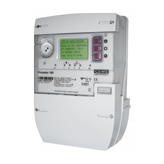
4.2 Front Panel of Prometer 100-R Figure 5: Front View The front cover is made of translucent plastic with a transparent window to view the display. The cover has two top hinges which allow the front cover to swing-up, allowing access to the sealed button and field replaceable battery. -
Page 10: Front Panel Of Prometer 100-W
4.3 Front Panel of Prometer 100-W Figure 7: Front View The front cover is made of translucent plastic with a transparent window to view the display. The top cover is used to seal the MD (Maximum Demand) reset button and field replaceable battery. The extended terminal block cover is secured in position by retaining screws and also has provision to seal it. -
Page 11: Connections To The Prometer 100-R
4.4 Connections to the Prometer 100-R The diagram shows the rear connector with its pin diagrams for the meter. There are different options that may be provided as per the specification agreed with the customer at the time of order. - Page 12 CT and H type for Aux and VT terminals. In case of Prometer 100-R the internal earthing cable between the meter and the rack should also be connected, and for this an M4 size screw is used in the meter and in the rack. The same ring type connector as used in the CT connection can also be used.
-
Page 13: Connections To The Prometer 100-W
4.5 Connections to the Prometer 100-W Connections to the Prometer 100-W are made on the meter terminal under the terminal cover. Connect R/L1 Y/L2 B/L3 Dual AUX P/+ Terminal N/- Terminal Supply CT IN AUX 1 CT OUT AUX 2... -
Page 14: Sealing Arrangement In Prometer 100 - R
4.6 Sealing Arrangement in Prometer 100 - R 4.6.1 Front Cover Sealing Transparent Window Translucent Front Cover Right-hand side Sealing & Locking point Left-hand side Sealing & Locking point Locking Screw & Sealing points Figure 13: Front Cover Sealing Arrangement The front cover can be sealed in the closed position. -
Page 15: Sealing Arrangement In Prometer 100 - W
Two pulse outputs (3 and 4 in case of Prometer 100-R / 2 and 3 in case of Prometer 100-W, refer to Figure 10 and Figure 12 for details) are linked to two pulse output LEDs indication as available on front side of meter so that user can have a visualisation sort of feature by physically seeing the LEDs. -
Page 16: Prometer 100 And M-Cubed Bcs
5 Prometer 100 and M-Cubed BCS This section describes the various operations that can be performed using the M-Cubed BCS with Prometer 100 meter. 5.1 M-Cubed BCS Figure 16: Prometer100 and M-Cubed BCS M-Cubed stands for Modular Meter Management and is the name of Secure’s software suite for programming meters, reading data and reporting from energy meters. - Page 17 BGX501-943-R01 Prometer 100 User Manual Page 17 of 72...
-
Page 18: Manual
Favourite: These are selected from the user configurable pages and up to 20 parameters can be selected in the field. • Configuration: Configuration page for Metrological LED, Display time out, Delete Favourite page displays, Reset Battery time, Meter Constant, MODBUS and language configuration. Page 18 of 72 Prometer 100 User Manual BGX501-943-R01... -
Page 19: Display Buttons
Parameters are cyclically displayed in the selected page, i.e. after the last parameter in the list is displayed, the display will return to the first in the list, and so on. Press the Enter button to return to the immediate parent page. BGX501-943-R01 Prometer 100 User Manual Page 19 of 72... -
Page 20: Menu Example Screens
Fixed Display Page Select the Fixed Display Page from the top line menu. The following screen will be displayed. Figure 19: Fixed Display Page The Fixed Display pages are shown below: Page 20 of 72 Prometer 100 User Manual BGX501-943-R01... - Page 21 Figure 20 below. The page title can have a maximum of 20 alphanumeric characters. The illustrations shown below are indications of how the pages and their respective displays will be displayed. The final pages and their corresponding displays are dependent on the specification of your purchase order. BGX501-943-R01 Prometer 100 User Manual Page 21 of 72...
- Page 22 Use the Up/Down buttons to scroll to the Instant Parameters page. The selection will be highlighted. Press the Enter button to open the page. Use the Up/Down buttons to scroll within the page and view the various screens. Page 22 of 72 Prometer 100 User Manual BGX501-943-R01...
- Page 23 BGX501-943-R01 Prometer 100 User Manual Page 23 of 72...
- Page 24 Use the Up/Down buttons to scroll to the Energy Registers page. The selection will be highlighted. Press the Enter button to open the page. Use the Up/Down buttons to scroll within the page and view the various screens. Page 24 of 72 Prometer 100 User Manual BGX501-943-R01...
- Page 25 Use the Up/Down buttons to scroll to the Demand Data page. The selection will be highlighted. Press the Enter button to open the page. Use the Up/Down buttons to scroll within the page and view the various screens. BGX501-943-R01 Prometer 100 User Manual Page 25 of 72...
- Page 26 Use the Up/Down buttons to scroll to the High Resolution Energy Registers page. The selection will be highlighted. Press the Enter button to open the page. Use the Up/Down buttons to scroll within the page and view the various screens. Page 26 of 72 Prometer 100 User Manual BGX501-943-R01...
- Page 27 Use the Up/Down buttons to scroll to the Previous IP Data registers page. The selection will be highlighted. Press the Enter button to open the page. Use the Up/Down buttons to scroll within the page and view the various screens. BGX501-943-R01 Prometer 100 User Manual Page 27 of 72...
- Page 28 Use the Up/Down buttons to scroll to the Miscellaneous information page. The selection will be highlighted. Press the Enter button to open the page. Use the Up/Down buttons to scroll within the page and view the various screens. Page 28 of 72 Prometer 100 User Manual BGX501-943-R01...
- Page 29 20 parameters can be selected in favourite display page. To delete the complete list of Favourite parameters, go to the configuration page and select ‘Del Fav Parameters’. BGX501-943-R01 Prometer 100 User Manual Page 29 of 72...
- Page 30 After completing the entry, press the Enter button to confirm. Correct password gives access to the first screen of configuration page. An incorrect password will display ‘Incorrect Password’ message. The Prometer 100 meter display can be set to different languages. The following languages are available: •...
- Page 31 Display to be added BGX501-943-R01 Prometer 100 User Manual Page 31 of 72...
- Page 32 (Russian and Arabic language options are missing in the above display) The following displays are self-explanatory and occur at the time of events such as configuration, file download etc. and are included here for your reference only. Page 32 of 72 Prometer 100 User Manual BGX501-943-R01...
- Page 33 Same for HV3 and HV4 to 30% Battery Status Less than 30% & Same for HV3 and HV4 Greater than equal to 20% Battery Status Less than 20% Same for HV3 and HV4 BGX501-943-R01 Prometer 100 User Manual Page 33 of 72...
-
Page 34: Events
Same for HV3 and HV4 6.5 Events The Prometer 100 has a number of defined events that are stored in the meter’s event log when they occur and restore. The events are arranged into different logical compartments with defined numbers of events logging. An event is displayed with a description and a time stamp in M-Cubed. -
Page 35: Functions
7 Functions This section provides an overview of the functions available in Prometer 100. All functions in the meter can be both configured and read in M-Cubed. In many cases, M-Cubed can also export data to a file or print out data. -
Page 36: Support For Different Types Of Energy
7.2 Support for Different Types of Energy Prometer 100 meter is used for feeder based applications where energy may flow in both the directions. Prometer 100 is an Import Export type meter; its metering unit is capable of logging energy in both directions. Active power export... -
Page 37: Instant Values
These registers cannot be reset. 7.3 Instant values Besides energy, the Prometer 100 can also measure instant values. Instant values are constantly changing values such as current, voltage, power and harmonics. The instant values are updated every second. The formulas and definitions used to calculate the values are presented in Appendix E: Calculation Principles on page 61. -
Page 38: Prefix For Units In The Display
7.4 Daily Energy Snapshot Energy Snapshot feature saves the value of a particular energy register at a particular time. Prometer 100 stores a snapshot of different energy registers (can be up to 28 energies) on a daily basis at predefined time as selected from tariff configuration (generally it is set at midnight). -
Page 39: Digital Inputs And Outputs
7.5 Digital inputs and outputs The Prometer 100 has several inputs and outputs that can be configured to perform various tasks. Both inputs and outputs are protected against overvoltages by varistors. They also have an isolated interface between the electronics and the surroundings to ensure personal safety. For electrical data on the meter’s inputs and outputs, see Appendix F: Connection and General Details (page 66). -
Page 40: Outputs
Note that the outputs are inverted via firmware. If the meter loses its auxiliary power, the relay will open, regardless of it is inverted or not. Page 40 of 72 Prometer 100 User Manual BGX501-943-R01... -
Page 41: Communications And Security
An active output means a closed relay when the output is not inverted. When the output is inverted, the active relay is open. The Prometer 100 outputs are of the solid-state type and when the meter is turned off, they are open. -
Page 42: Loggers
7.7.1 Overview A logger in a Prometer 100 can log values for instant quantities, energy registers and external registers. Some quantities can be logged both by phase and as total values for all three phases, others only as total values. The table provides an overview of quantities that can be logged. -
Page 43: Logging Interval And Total Channels
A logger’s capacity is dependent on number of channels and logging interval. For example, Prometer 100 meters can be configured to store 960 days of load profile data at 30 minutes SIP for 10 parameters. When the logger is full, the oldest values will be written over. The table shows the capacity in number of days before the oldest value is written over. -
Page 44: Storage Of Logged Values
When a user-defined alarm has triggered during the past interval, this is indicated with the flag “Alarm”. Parameter The Prometer 100’s configuration, calibration or initiation has changed. Which of changed these three the flag refers to can be seen in the event log. -
Page 45: Alarms
7.8 Alarms The Prometer 100 is equipped with alarms to be able to indicate when measured quantities are over or under a factory configured limit value. The meter enters the alarm state when the limit value is reached. An alarm is generated only after the alarm state has continued for a configurable time (persistence time). -
Page 46: Indication
Phase wise PT Miss Over Voltage Under Voltage Voltage Unbalance Phase wise CT Reversal Phase wise CT Open (HT Meter Only) CT Bypass (HT Open Only) Current Unbalance Power Fail / Power On-Off Page 46 of 72 Prometer 100 User Manual BGX501-943-R01... -
Page 47: Maximum Demand
The Prometer 100 meter has the capability of logging Maximum Demand for all the selected energy types (except Net Active and Net Reactive). The Maximum Demand is computed for a fixed block of time which is called Demand Integration Period (DIP). -
Page 48: Historical Registers
7.10 Historical registers Historical registers are used by the Prometer 100 to store current register values at defined points so as to be able to read them later. Stored in historical registers are all maximum demand values, TOU registers and energy registers, with the exception of energy registers by phase. -
Page 49: Day Type
A holiday date specifies the day type that applies on a certain date. Holiday dates can be configured to apply every year on the same date or for a single year. In the Prometer 100, up to 30 holiday dates can be configured. -
Page 50: Cumulative Maximum Demand Registers
7.13 Meter Reading The Prometer 100 uses DLMS for meter reading. In DLMS protocol the BCS is considered the client and the meter is the server. On request by the BCS, the meter will send all its supported OBIS codes and expected queries. -
Page 51: Instrument Transformer Compensations
The states shorter than three seconds are registered by accumulating registers. If the states last longer than three seconds, they are instead registered in the event log with time stamp and duration. The accumulating counters and the event log can be read in M-Cubed. BGX501-943-R01 Prometer 100 User Manual Page 51 of 72... -
Page 52: Appendix A: Abbreviations
Supervisory Control and Data Acquisition Maximum Demand UMD: Universal Maximum Demand (0 to 24 hours) Appendix B: Material Declaration The material declaration for the Prometer 100-R is shown below: Enclosure Rack Mild steel with Aluminium Meter Enclosure Mild steel Meter back plate... -
Page 53: Appendix C: Communication Ports
Optical Communication Port In Prometer 100-R, the optical 1107 port is protected by a sliding cover. The 1107 optical port cover can be slid upwards in the arrow direction to the open position. The cover has a captive design and cannot be removed and lost. - Page 54 RS485 Serial Communication Port The RS485 serial half duplex communication ports are intended to be used to connect the Prometer 100 to a network for multi-drop communications. The RS485 network is looped through the input connector to the output connector.
-
Page 55: Appendix D: How To Read Meters Through Ethernet Port
The Ethernet port has a 1-minute inactivity time-out period. If no activity is detected the Ethernet port will disconnect after 1 minute. Appendix D: How to Read Meters through Ethernet Port This section discusses the reading a Prometer 100 meter through Ethernet port (TCP/IP connection). Prerequisites: Take static IP address, Subnet Mask and Gateway from network M-Cubed (6.0.0.6) - Page 56 Check successfully connected Click Transaction and then click TCP/IP Configuration Enter the IP address, Subnet Mask and Gateway information to be configured in meter. Click OK Page 56 of 72 Prometer 100 User Manual BGX501-943-R01...
- Page 57 Scroll down to view the Ethernet configuration information Reading the Prometer 100 Meter on the Ethernet port Connect the meter with the LAN network using the LAN cable. Confirm that the LAN cable is firmly connected to both the meter and PC Ethernet ports.
- Page 58 “Use TCP profile over Ethernet port.” Enter the meter static IP information in Connection Address Click OK. Static IP is 172.16.13.5 Service port is 4059. It is fixed for DLMS Page 58 of 72 Prometer 100 User Manual BGX501-943-R01...
- Page 59 Meter connected successfully with the M-Cubed. BGX501-943-R01 Prometer 100 User Manual Page 59 of 72...
- Page 60 To read data, click Get All Data Action completed successfully will be displayed. Page 60 of 72 Prometer 100 User Manual BGX501-943-R01...
-
Page 61: Appendix E: Calculation Principles
For 2-element meters, only the total power is calculated in each harmonic component. ϕ Phase angle between harmonic component ϕ U 32 Phase angle between harmonic component ϕ ϕ ⋅ ⋅ ⋅ cos( cos( BGX501-943-R01 Prometer 100 User Manual Page 61 of 72... - Page 62 (e.g., active power >= 0 and reactive power >= 0 corresponding to quadrant I). Reactive energy import: quadrant I and II Active energy export: quadrant III and IV Reactive energy inductive: quadrant I and III Page 62 of 72 Prometer 100 User Manual BGX501-943-R01...
- Page 63 Phase angle values specified between –180 ° and 180°. Total harmonic distortion ⋅ − Where … are the current’s harmonic components. The calculation is made in the same ways for current and voltage. BGX501-943-R01 Prometer 100 User Manual Page 63 of 72...
- Page 64 Phase current. Nominal current. ⋅ ⋅ CuLoss meas Corresponding calculations made for active and reactive power. Definition of phase order Correct phase order (123) corresponds to phase position: Phase position for U1 Page 64 of 72 Prometer 100 User Manual BGX501-943-R01...
- Page 65 ° = 120 − ° = 120 ° The same system is represented graphically below. The vectors rotate in an anti-clockwise direction. BGX501-943-R01 Prometer 100 User Manual Page 65 of 72...
-
Page 66: Appendix F: Connection And General Details
Wiring configuration 3-phase 3-wire, 3-phase 4-wire 57.7/100 V to 69.3/120 V (configurable) for HV3 & HV4 Voltage range (L-N/L-L) 240/415 V for LV4 (applicable for Prometer 100-W only) : 1-5 A (configurable) Current range : maximum 10 A (configurable) Accuracy Class 0.2s and 0.5s... - Page 67 C to + 70 C (limit range of operation) Temperature C to + 80 C (storage) C to + 70 C (display operating range) Humidity 95% non-condensing Pollution degree Type 2 Over voltage category BGX501-943-R01 Prometer 100 User Manual Page 67 of 72...
-
Page 68: Appendix G: List Of Dlms Parameters
Voltage THD % - Phase 3 Instantaneous 3rd Harmonic Voltage - Phase 3 Instantaneous 5th Harmonic Voltage - Phase 3 Instantaneous 7th Harmonic Voltage - Phase 3 Instantaneous 9th Harmonic Voltage - Phase 3 Page 68 of 72 Prometer 100 User Manual BGX501-943-R01... - Page 69 Current THD % - Phase 3 Instantaneous 3rd Harmonic Current - Phase 3 Instantaneous 5th Harmonic Current - Phase 3 Instantaneous 7th Harmonic Current - Phase 3 Instantaneous 9th Harmonic Current - Phase 3 BGX501-943-R01 Prometer 100 User Manual Page 69 of 72...
-
Page 70: Frequently Asked Questions (Faqs)
M-Cubed 100 and via the communication protocol. Which information is not available on the Prometer 100’s display for 3-phase 3-wire? On configuring Phase 2 displays for 3-phase 3-wire, the Phase 2 parameters such as energy, voltage, current, Power, P.F, harmonics, L1-L2 voltage phase angle, L2-L3 voltage phase angle and current symmetry data will... - Page 71 What are the possible consequences of adjusting backward or forward the meter clock within time adjustment limit? Integration period will be compressed for forward time sync and stretched for backward time sync. Data will be logged as per integration period. BGX501-943-R01 Prometer 100 User Manual Page 71 of 72...
- Page 72 Cewe Instrument AB Box 11006, SE 611 29 Nyköping Sweden : +46 155 775 00 +46 155 775 97 UK contact details : +44 (0) 1962 840048 +44 (0) 1962 841046...
Need help?
Do you have a question about the Prometer 100 and is the answer not in the manual?
Questions and answers