
Related Manuals for Cassese CS 79


Summary of Contents for Cassese CS 79
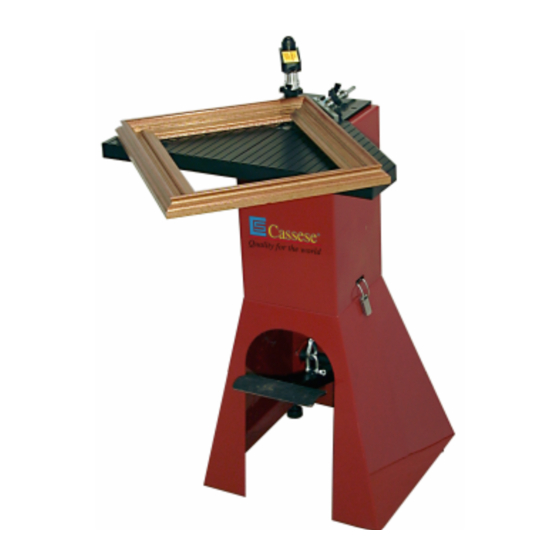
- Page 1 Quality for the world CS 79 Technical and User Manual V1 - 07 / 99 Cassese / Communication...
- Page 2 CS 79 PERATED RAME SSEMBLING ACHINE Fig N°1 Fig N°3 ANGLE ADJUSTMENT SCREW LIMIT STOP BACKFENCE BACKFENCE ROTATING BASE CABINET 90° JOINING ANGLE ASSEMBLY WIRE FOR WEDGE PUSHING SPRING WEDGE DISTRIBUTOR LEVER FOR STAPLING POSITION (inside of frame) LEVER FOR...
-
Page 3: Table Of Contents
CS 79 - USER’S TECHNICAL MANUAL CONTENTS Page INTRODUCTION ACCESSORIES SUPPLIED WITH THE MACHINE TECHNICAL SPECIFICATIONS OPTIONS GUARANTEE PUTTING INTO OPERATION REASSEMBLY ADJUSTMENTS SELECTION OF STAPLING POSITIONS SETTING AND STORING THE STAPLING POSITIONS SELECTION OF TOP PRESSER ADJUSTMENT OF THE ASSEMBLY ANGLE... -
Page 4: Introduction
INTRODUCTION You have just bought a CS 79 frame joining machine, so we congratulate on your sensible choice and thank you for your trust in Cassese products. The CS 79 benefits from the experience of the joining machines that brought Cassese a cer- tain reputation. -
Page 5: Putting Into Operation
PUTTING INTO OPERATION 1 ) UNPACKING & REASSEMBLY fig.A Fig C Fig B - Keep the package of the machine so, that the arrows drawn on the outside stand up, (see Fig A) - Open the parcel. Remove machine’s table Ta and the foam protection (see Fig. B). - (See Fig C) Pressing down the crossing wood piece B, loosen and remove one of the two feet of the machine that are holding the wood piece B in place. - Page 6 BOTTOM PULLEY DEVICE HOLDING CABLE IN PLACE - Now put the machine CS 79 up on its feet; - Fix the extension table Ta with the 4 screws VT (see Fig.J). - Adjust the level of the machine with its 4 feet so that it is stable during operation.
-
Page 7: Adjustments
SELECTION OF STAPLING POSITIONS The CS 79 is designed to join mouldings in one or two places (positions) without limitation of the number of wedges in any of those places. The selection depends on the width and thickness of the moulding to join. - Page 8 Standing in the work position used of reference for explanations (behind the machine; see Fig 2, page 1), with your left hand, put the first moulding chop in front of the left (1 backfence B1 and bring the chop in contact with the right (2 ) backfence B2.
-
Page 9: Selection Of Top Presser
(chop service), the angles of the mouldings will be slightly different from one cutting machine to the other. The joining angle of your CS 79 can be adapted to find precisely the cutting angle of your cutting machine. -
Page 10: Use
: NORMAL for soft and normal timbers and HW for very hard timbers. These hardwood wedges are to be used only on hardwoods. Your CS 79 machine is designed to use all sizes of Cassese cartridges without having to change any parts on the machine or having to adjust anything. -
Page 11: Maintenance
MAINTENANCE 1) LUBRICATION Periodically, remove the wedge distributor (Fig 1, block H) and clean it (by air gun) without dis- mounting it. It is recommended to lubricate the hammer (driver blade) periodically. To do so, remove the wedge distributor (blockH) and put a small quantity of grease in the bottom hole of the wedge distributor. The hammer will be lubricated every time it crosses the wedge distributor. -
Page 12: Clearing A Wedge Stuck In The Wedge Distributor
MAINTENANCE 3 ) IN CASE OF HAMMER AND WEDGE JAMMING AFTER EACH INCIDENT, IF THE HAMMER STAY JAMMED IN BLOCK H, YOU SHOULD HAVE TO CHANGE IT WEDGE DISTRIBUTOR (BLOCK H) LOCKING SCREW SCREW POSITIONS BLOCK H - Remove the cartridge that is on machine, and the top presser. - Using the 3mm Allen key, loosen the locking screw of the wedge distributor Block H. -
Page 13: Replacement Of Battery
REPLACEMENT OF BATTERY OF WEDGE-FULLY-INSERTED INDICATOR Remove the cable of the foot pedal from hook M (Fig. F, page 3). With a 5mm Allen key (supplied in the accessory box), undo and remove the 4 screws A-B- C-D that fix the mechanism of the machine to the upper cabinet. See picture above. Battery 9 V Now, you can remove the mechanism out of the cabinet and access to the battery that is a standard 9 V one. -
Page 14: New Version Top Presser
NEW VERSION TOP PRESSER (item # Z6232) This new version top presser comes now with your CS 79 as a standard feature. Its height can be adjusted with the pin so that the ma- chine can work up to 78 mm (3”1/8) tall mouldings.
Need help?
Do you have a question about the CS 79 and is the answer not in the manual?
Questions and answers
manual de refacciones ensambladora CS79
The parts manual for the Cassese CS 79 assembly machine is titled "CS 79 Technical and User Manual V1 - 07 / 99."
This answer is automatically generated