Table of Contents
Advertisement
The information contained in this manual remains the property of Gigawave and may not
be used, disclosed or reproduced in any other form whatsoever without the prior written
permission of Gigawave.
D-Cam Clip-On
OPERATORS MANUAL
Copyright 2005 Gigawave Limited
D-Cam Clip-On Operators Manual
Issue 1
Page 1 of 1
UNUM-CCAM -0104
Advertisement
Table of Contents

Subscribe to Our Youtube Channel
Related Manuals for Gigawave D-Cam Clip-On

Summary of Contents for Gigawave D-Cam Clip-On
- Page 1 The information contained in this manual remains the property of Gigawave and may not be used, disclosed or reproduced in any other form whatsoever without the prior written permission of Gigawave. D-Cam Clip-On OPERATORS MANUAL Copyright 2005 Gigawave Limited D-Cam Clip-On Operators Manual...
-
Page 2: Table Of Contents
3.4.2 FW Inventory........................13 3.4.3 Video Input ........................13 3.4.4 Video Format........................14 3.4.5 Temperature.........................14 PREPARING FOR OPERATION..................18 4.1 The D-Cam Clip-On Camera Back...................18 4.2 The Receiving Equipment....................18 D-Cam Clip-On Transmitter ....................20 5.1 Connector Pin Outs......................20 5.1.1 SDI / CVBS Video BNC ....................20 5.1.2 Video Connector......................20... -
Page 3: General Safety Information
NOTE: The manufacturer is not responsible for any radio or TV interference caused by unauthorized modifications to this equipment. Such modifications could void the user's authority to operate the equipment. D-Cam Clip-On Operators Manual Issue 1 Page 3 of 3... -
Page 4: Health & Safety
The unit is supplied with a 4dBi antenna that is fitted to the rear of the camera. The FCC RF Exposure Evaluation has determined that a 20cm minimum safety distance must be maintained between the antenna and all persons in the area. Use of the unit with an external mast mounted antenna and / or power amplifier requires separate RF Exposure Evaluation. -
Page 6: Introduction
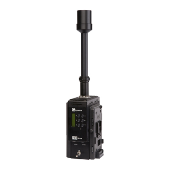
2 INTRODUCTION This manual is to be used in conjunction with the D-Cam Clip-On unit (CCAM-0104) which replaced the original 0101 & 0102 variants. The upgrade from 0101 to 0102 added the extra feature of an SDI input. The upgrade from 0102 to 0104 added the extra features of frequency selection to 0.5MHz increments. - Page 7 POWER CAMERA BATTERY RF OUTPUT AMPLIFIER INTERFACE CLIP igawave igawave -Cam STATUS -Cam VIDEO AUDIO 12V DC External Views of the D -Cam Clip-On D-Cam Clip-On Operators Manual Issue 1 Page 7 of 7 UNUM-CCAM -0104...
-
Page 8: System Operation
Clip-On, see 3.4.3 for details of the hardware configuration via the Control Panel. If a battery is docked onto the rear of the D-Cam Clip-On, no external DC power lead is required. This is only required to provide power to the D-Cam Clip-On and camera if a battery belt / external power supply is used. - Page 9 CH16 2492 .00MHz Mem0 – 64QAM 18M CHANNEL / FREQUENCY 3.2.4 MAIN ? ENCODER ? ENCODER Mem 0 – 64QAM 18M ENCODER ? 3 .2.5 Mem 7 – QPSK ENCODER D-Cam Clip-On Operators Manual Issue 1 Page 9 of 9 UNUM-CCAM -0104...
- Page 10 MAIN ? AUDIO 2 AUDIO 2 Input ? AUDIO 2 Select INPUT LINE AUDIO 2 Input ? 3.2 .7 AUDIO 2 AUDIO 2 Level Set LEVEL 0.0dB AUDIO 2 D-Cam Clip-On Operators Manual Issue 1 Page 10 of 10 UNUM-CCAM -0104...
- Page 11 STATUS ? STATUS Video Input STATUS ? 3.2 .3 TS Present STATUS ? TS Rate STATUS ? Synth Lock STATUS ? PA Enabled STATUS ? RF Output STATUS D-Cam Clip-On Operators Manual Issue 1 Page 11 of 11 UNUM-CCAM -0104...
-
Page 12: Ch / Frequency Menu
As 3.2.5 above but for setting the Audio 2 input and level. 3.2.7 Status Menu The status menu is used to confirm the condition of the D-Cam Clip-On. If the Status LED is red indicating a fault or warning, the Status menu will indicate the nature of the problem. -
Page 13: Status Monitoring
3.4.3 Video Input The D-Cam Clip-On can accept CVBS via the BNC input, or CVBS, YC, YUV via the six pin LEMO Video input. SDI digital video can also be input via the BNC 75Ω connector if required this can also be used to input CVBS analogue video. -
Page 14: Video Format
NTSC (525/60). The Enter button then stores the value and returns to the Main menu. 3.4.5 Temperature A display in degrees Celsius of the internal temperature of the D-Cam Clip-On controller. D-Cam Clip-On Operators Manual Issue 1 Page 14 of 14... - Page 15 ENGINEERING MENU E to Enter & store program C to Cancel 3.4.1 ENG MENU PROG CHANNEL ? PROG PROG CHANNELS 1990.00 MHz 1990.00 MHz PROG CHANNEL ? PROG Ch16 2492.00 MHz Ch16 2492.00 MHz PROGRAM CHANNELS 3.4.2 ENG MENU FIRMWARE ? FW INVENTORY FP Ver 03.01 FIRMWARE ?
- Page 16 3 .4 .2 3.4.3 ENG MENU VIDEO INPUT ? VIDEO INPUT VIDEO INPUT ? CVBS VIDEO INPUT ? VIDEO INPUT ? VIDEO INPUT 3.4.4 ENG MENU VIDEO FORMAT ? VIDEO FORMAT VIDEO FORMAT ? 3.4.5 NTSC VIDEO FORMAT D-Cam Clip -On Operators Manual Issue 1 Page 16 of 16 UNUM-CCAM-0104...
- Page 17 3 .4 .4 3.4.5 ENG MENU TEMPERATURE TEMPERATURE 49.6 C TEMPERATURE 3 .4 .1 D-Cam Clip -On Operators Manual Issue 1 Page 17 of 17 UNUM-CCAM-0104...
-
Page 18: Preparing For Operation
To enable the frequency to be checked without transmitting RF power the D-Cam Clip-On can be powered up with the PA disabled. To disable the RF Power Amplifier the C and ? are pressed as the D-Cam Clip-On is switched on. - Page 19 The Receiver Head and Control units may be operated at distances up to 600 metres apart. Gigawave triax cable is supplied in standard lengths of 100 and 200 metres and will plug together to create the lengths required. Check that the necessary lengths of triax interconnecting cable are available and that the cable and cable connectors are in serviceable condition.
-
Page 20: Cam Clip-On Transmitter
• Display / System Controller PBAB-TDDB-0101 The superior RF performance of the D-Cam Clip-On when combined with a MVL -D Series Receiver is such that it requires only a single receive point with Fanbeam antenna for most normal OB locations, including sports stadiums. -
Page 21: Audio Connector
This connector can be used to take power from the docked battery (5A Max) to power external cameras if the D-Cam Clip-On is not docked directly to the camera, or feed power into the D -Cam Clip-On and then forward into the camera. -
Page 22: Audio / Video Encoder
9-18V battery supply. These include 2.5, 3.3V, 5V, 8V and +/-5V supplies. There are no field replaceable parts on the Encoder board. If a fault occurs with the board, contact Gigawave for technical assistance. D-Cam Clip-On Operators Manual Issue 1... -
Page 23: Cofdm Modulator
1/32 6.032086 QPSK 1/32 6.032086 There are no field replaceable parts on the COFDM modulator. If a fault occurs with the board please contact Gigawave for technical assistance. D-Cam Clip-On Operators Manual Issue 1 Page 23 of 23 UNUM-CCAM -0104... -
Page 24: Power Amplifier
Front Panel by the operator. These parameter sets are held in the non- volatile memory of the front panel unit and can only be upgraded by the factory. D-Cam Clip-On Operators Manual Issue 1 Page 24 of 24... -
Page 25: Default Parameter Set
SP@ML, Infinite 6.00 0303-05-05 3/4, 1/32 GOP, Intra-slice PBSW-TDVP - 6.032086 QPSK SP@ML, 4.94 0303-05-06 1/2, 1/32 Infinite GOP PBSW-TDVP - 6.032086 QPSK MP@ML, 4.94 0303-05-07 1/2, 1/32 GOP4 D-Cam Clip-On Operators Manual Issue 1 Page 25 of 25 UNUM-CCAM -0104... -
Page 26: System Monitoring / Setup
6 System Monitoring / Setup Using a PC running Hyper Terminal or other terminal emulator, the D-Cam Clip-On can be configured without the use of the operator controls and LCD display. The current configuration can also be obtained via this RS232 interface. -
Page 27: Program Channels
Ch8 2375 MHz Ch9 2400 MHz Ch10 2425 MHz Ch11 2450 MHz Ch12 2475 MHz Ch13 2500 MHz Ch14 2525 MHz Ch15 2550 MHz Ch16 2575 MHz > D-Cam Clip-On Operators Manual Issue 1 Page 27 of 27 UNUM-CCAM -0104... -
Page 28: Program Channel
The Ch number ( 1-16) is first selected; then a four digit frequency. This frequency input is range checked to confirm that the input frequency is valid ‘L’ist can then be used to display the current channel allocation. D-Cam Clip-On Operators Manual Issue 1 Page 28 of 28... -
Page 29: Dump Setup
> This provides a complete listing of the current configuration, this can then be ‘cut & paste ‘ and saved to form a record of the unit configuration. D-Cam Clip-On Operators Manual Issue 1 Page 29 of 29 UNUM-CCAM -0104... -
Page 30: Unit Name
ID for the D -Cam Clip-On e.g. RF Cam#1. This name can be up to sixteen characters long, one line of the LCD display. All sixteen characters must be entered, spaces are used to complete the line as required. D-Cam Clip-On Operators Manual Issue 1 Page 30 of 30...
Need help?
Do you have a question about the D-Cam Clip-On and is the answer not in the manual?
Questions and answers