Table of Contents
Advertisement
The information contained in this manual remains the property of Gigawave and may not be used,
disclosed or reproduced in any other form whatsoever without the prior written permission of
Gigawave.
Gigawave reserves the right to alter the equipment and specification appertaining to the equipment
described in this manual without notification.
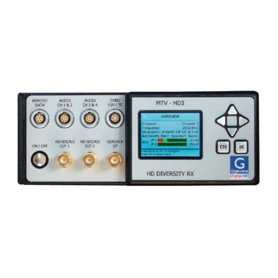
MTV-HD3 RECEIVER
H264/MPEG-4 and MPEG-2 version
OPERATOR'S MANUAL
Copyright 2011 Gigawave Limited
MTV3- ASUM-7001-07
page 1 of 25
Advertisement
Table of Contents

Related Manuals for Gigawave MTV-HD3

Summary of Contents for Gigawave MTV-HD3
- Page 1 The information contained in this manual remains the property of Gigawave and may not be used, disclosed or reproduced in any other form whatsoever without the prior written permission of Gigawave. Gigawave reserves the right to alter the equipment and specification appertaining to the equipment described in this manual without notification.
-
Page 2: Table Of Contents
CONTENTS GENERAL INFORMATION ..................... 4 General safety instructions ....................4 Disposal Instructions ......................4 Environmental ........................4 Health & Safety ........................5 Maximum RF Power Density Limits .................. 6 Issue Status ........................6 GENERAL DESCRIPTION ...................... 7 RECEIVER SPECIFICATIONS ....................8 PIN CONNECTIONS ...................... - Page 3 USB upgrade......................19 5.5.8 Decryption ........................20 5.5.9 Receiver menu Tree ....................21 PREPARING FOR OPERATION ................... 23 The MTV-HD3 receiver ..................... 23 6.1.1 Antennas ........................23 6.1.2 Checks ........................23 Transmitter / Receiver tests..................... 23 TABLE OF COFDM BIT RATES ................... 24 DVB-T bit rates .........................
-
Page 4: General Information
Avoid standing in front of high gain antennas (such as a dish) and never look into the open end of a waveguide or cable where RF power may be present. Users are strongly recommended to return any equipment that requires RF servicing to Gigawave. WARNING- GaAs / BeO Hazard: Certain components inside the equipment contain Gallium Arsenide and Beryllium Oxide that are toxic substances. -
Page 5: Health & Safety
It is important to note that the guidelines adopted differ throughout the world and are from time-to-time re-issued with revised guidelines. For Gigawave use, a maximum power density limit (w) of 1w/m² is to be applied when calculating minimum safe working distances. -
Page 6: Maximum Rf Power Density Limits
Different power density / frequency characteristics are presented in the two documents. To avoid complexity and to avoid areas of uncertainty, Gigawave recommends the use of a single power density limit across the frequency range 100 KHz to 300 GHz. The 1w/m² power density limit we recommend satisfies the most stringent of the guidelines published to date. -
Page 7: General Description
Full details are given in the Gigawave Antennas data sheet. At the transmitting site a range of Gigawave digital transmitters may be used; for example the complementary MTV-HD2 and D-Cam Clip-On, and MVL-D2 transmitters are available in both H264 and MPEG-2 versions. -
Page 8: Receiver Specifications
(500kHz steps available to special order) Receiver Noise Factor 4dB max. Receiver Threshold -92dBm to BER 10-5 (nom., QPSK) Receive Antenna Compatible with all Gigawave antennas Demodulation Maximum Ratio Combining Diversity reception Demodulation Modes DVB-T 2k... - Page 9 To spec: -10° to +45°C Altitude: 4500m Humidity: 95% long term Mechanical Interface Standard wedge plate compatible with all Gigawave interfaces. Specifications may alter at the discretion of Gigawave or to meet customer specific requirements. MTV3- ASUM-7001-07 page 9 of 25...
-
Page 10: Pin Connections
4 PIN CONNECTIONS Front panel 4.1.1 SDI /ASI Two outputs for either SDI or ASI. Each may be independently selected via front panel menu system. See 5.5.4 75 BNC connector 4.1.2 Genlock input Reference input for Genlock. Analogue CVBS or Tri level sync. 75... -
Page 11: Audio Connectors
4.1.4 Audio Connectors Line level output AUDIO CH 1 & 2 Connector Type: 8 pin LEMO connector EGG.1B.308.CLN 1 channel AES3/EBU Stream, plus 2 x analogue (mono) audio outputs Analogue Ground A1 / Left +ve A1 / Left -ve A2 / Right +ve A2 / Right -ve Digital Ground Digital +ve... -
Page 12: Remote Control/User Data Connector
7 pin LEMO connector EGG.1B.307.CLN Dual purpose connector User data output - RS232, see 5.5.6.1 MTV-HD3 RECEIVER remote control using RS232 or RS485, factory option (alternative to remote control via Ethernet, see 4.2.4) note User Data Tx (out) User Data Rx (in) -
Page 13: Rf Inputs (2 Way Diversity)
4.2.3 RF Inputs (2 way diversity) Connector Type: 50Ω N (F) - quantity 2 4.2.4 USB / Ethernet Connector Type: 8 pin LEMO connector EGG.1B.308.CLN Dual purpose connector Ethernet port for remote control and monitoring (web browser interface), see 5.5.6.3 ... -
Page 14: Configuring The Receiver
The OK button is used to store a modified parameter in non-volatile memory, this parameter will then be used to configure the MTV-HD3 receiver and will also become the default value when next powered on. The ESC button can be used to exit a menu without storing the parameter in memory. -
Page 15: Status And Alarm Screens
When the receiver is locked to the transmitter and there are no alarms the button at the top left will show green. 5.4.2 Status and alarm screens These screens are accessed from the Overview screen by repeatedly pressing the ► button. 5.4.2.1 Signal status The following functions are displayed:- ... -
Page 16: Decoder Information
5.4.2.3 Decoder information The following functions are displayed:- ASI status Network name Transport stream rate Compression type MPEG-2 or H264 Video format Genlock status 5.4.2.4 Unit status and alarms Provides the alarm status of individual modules within the receiver Setup menus To access the setup menus from the Status screens press the OK button. -
Page 17: Frequency
5.5.1.2 Frequency Displays the frequencies assigned for the 16 preset channels. The ‘Man’ setting allows the transmit frequency to be set in 1MHz steps anywhere within the TX operating band. The OK button allows the ◄► buttons to select the required digit, the ▲▼ buttons then select the required value. -
Page 18: Audio Output Impedance
5.5.4.1.3 Audio output impedance The analogue audio output impedance may be set to either 600 Ohms or Low impedance Note: This function is only available in Advanced/Enabled. See 5.5.7.4 5.5.4.2 Digital outputs The two BNC digital outputs on the receiver front panel may independently be set to: Either - SDI –... -
Page 19: Ethernet Port
5.5.7.5 USB upgrade This feature allows the software in the MTV-HD3 receiver to be upgraded via the USB port on the rear panel of the unit. Instructions for the upgrade procedure are provided by the factory with the new software. -
Page 20: Decryption
EU ETSI scrambling algorithm, BISS modes 1 and E. Set up of the BISS de-scrambling keys is through this menu. The MTV-HD3 receiver may either be configured to use a single key for all receiver channels, or allow different keys for each channel. -
Page 21: Receiver Menu Tree
5.5.9 Receiver menu Tree Note: Items shown in green are only available in Advanced mode. Channel frequency Channel Frequency Spectrum and Bandwidth Bandwidth Automatic spectrum Genlock Type Required Signal Line Offset Pixel Offset Inputs Decoder signal loss Blue screen Last image Outputs Analogue Video type... - Page 22 Output ports User data Interface type Baud rate Parity Remote Local Int type Ethernet Enable/disable Allow SSH General settings Software version Display Theme Unit name Advanced mode Enable / disable Change PIN USB upgrade Decryption Configure Enable/disable Per Ch. Setup Unit setup or channel X setting BISS level BISS-1 key...
-
Page 23: Preparing For Operation
The MTV-HD3 receiver 6.1.1 Antennas The MTV-HD3 receiver can be used with a variety of Gigawave antennas; for information please see the Gigawave Antennas data sheets. 6.1.2 Checks The receiver may be powered from an external DC PSU, or by batteries. Check that any batteries to be used are fully charged and that an emergency spare battery is available and fully charged. -
Page 24: Table Of Cofdm Bit Rates
7 Table of COFDM bit rates DVB-T bit rates DVB-T Bit Rates - 6 MHz CODE Guard interval = 1/32 Guard interval = 1/8 Guard interval = 1/4 RATE QPSK 16QAM 64QAM QPSK 16QAM 64QAM QPSK 16QAM 64QAM 4.52 9.08 13.57 4.14 8.29... -
Page 25: Isdb-T Bit Rates
ISDB-T bit rates ISDB-T Bit Rates - 6 MHz CODE Guard interval = 1/32 Guard interval = 1/8 Guard interval = 1/4 RATE QPSK 16QAM 64QAM QPSK 16QAM 64QAM QPSK 16QAM 64QAM 4.43 8.85 13.28 4.06 8.11 12.17 3.65 7.30 10.95 5.90 11.80...
Need help?
Do you have a question about the MTV-HD3 and is the answer not in the manual?
Questions and answers