Page 1
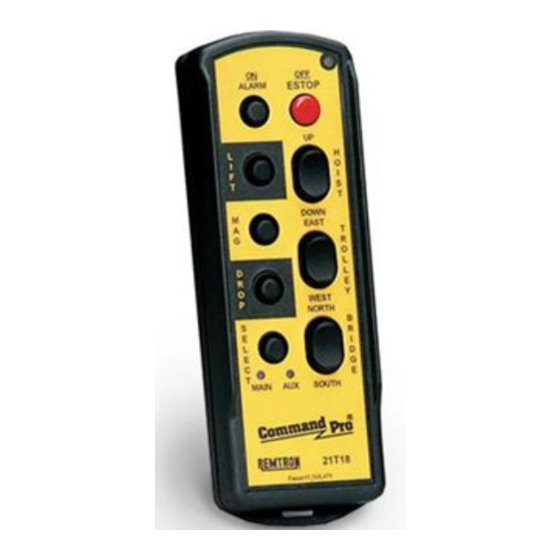
REMOTE CONTROL AND TELEMETRY SYSTEMS Radio Remote Control System User's Manual This manual covers the following Remtron models: Transmitters Receivers 21T10 21R10 21T14 21R14 21T18 21R22 21T20 21T23 21T34 21T44 AVERTISSEMENT ! WARNING ! Read all Safety and Warnings before Lire toutes les consignes de sécurité...
Page 3
WARNING INSTRUCTIONS WARNING ! READ ALL INSTRUCTIONS Failure to follow the SAFETY RULES may result in serious personal injury. INSTALLATION * GROUND THE RECEIVER CASE. In order to insure safety of the system, the receiver case must be firmly connected to earth ground. * PROVIDE A SAFETY CUTOFF SWITCH.
Page 4
CONSIGNES DE SÉCURITÉ A V E R T I S S E M E N T ! LIRE TOUTES LES CONSIGNES Le non respect des CONSIGNES DE SÉCURITÉ peut causer des blessures sérieuses. INSTALLATION * RACCORDER LE BOÎTIER À LA MASSE. Pour que le système fonctionne en toute sécurité, le boîtier du récepteur doit être solidement raccordé...
A key feature of and the Microprocessor based control system. Signals the hand held transmitters is Remtron's patented switch are received by an advanced synthesized RF module assembly for control inputs. This long life elastomeric that operates in conjunction with the microprocessor.
SECTION 1: SYSTEM DESCRIPTION The following options are only available on the 220 VAC, 50/60 Hertz, 250 VDC and other power inputs are available. The input is protected by a fuse. 21R22 receiver: Safety Features Stepless (proportional) Outputs: Controlling heavy industrial equipment requires that the External Hard Wire Inputs.
SECTION 2: INSTALLATION 2.1 INSTALLATION PLANNING 2.3 ANTENNA MOUNTING To ensure reliable and safe operation of the system, the The antenna is one of the most important parts of a radio following points must be considered before installing the receiving system. The receiver is designed with a specially receiver assembly.
Page 8
The safety of this system depends on the Mount the receiver cabinet securely to a solid surface. proper wiring of this switch. Call Remtron Use appropriate locking type hardware to prevent Applications Engineers if you have any loosening. Refer to Figure 6.1.
Page 9
SECTION 2: INSTALLATION controls when the switch is in the pendant position. It Installation Testing. should also be wired to transfer control between the pendant and the radio circuits. Before putting the system into service, the following tests must be performed. Output Relay Connections.
SECTION 3: TROUBLESHOOTING 3.1 GENERAL If the LED remains on continuously there is either a switch activated at the time the transmitter is turned on, The following procedures are for diagnosing problems or a general failure that requires factory service. If the within the system and isolating them down to the module LED remains lit continuously on power-up, insure that no other switches are pressed while attempting to turn...
Page 11
SECTION 3: TROUBLESHOOTING SIGNAL - This will flash each time a signal is being Check the POWER on indicator. If it's not lit, make received. For the 21R22 receiver, this also indicates sure the power switch on the right hand side of the a proper address was received.
Page 12
SECTION 3: TROUBLESHOOTING are firmly snapped in place and that the RF/Decoder board is firmly attached to the back of the Relay board. Check antenna connections. If Operating Range is short, Check all antenna connections and the transmitter operation. On new installations, verify the receiver antenna is placed properly.
SECTION 4: MAINTENANCE 4.1 PERIODIC MAINTENANCE 4.3 PROGRAMMING Once a year inspect the transmitter for damage to the Each transmitter and receiver can be programmed for keypad and case. any operating frequency, address code and specific operating parameters required by the particular system. Once a month all electrical and antenna connections Each system is fully programmed and tested before should be inspected.
SECTION 4: MAINTENANCE as well as programming of application information. This Programming is recommended for larger installations that must maintain systems with a variety of configurations. The transmitter and receiver are programmed using the same method. A stand alone programmer, RAC16, is available for most applications.
PH 760-737-7800 Tables 5.1 and 6.1 list the spare parts available from 4.6 Warranty Remtron for field repair of the transmitter and receiver. Detailed parts lists and schematics are available to support Remtron, Inc. warrants its material handling products to depot level maintenance activities.
Need help?
Do you have a question about the Command Pro 21T10 and is the answer not in the manual?
Questions and answers