Table of Contents
Advertisement
Advertisement
Table of Contents

Related Manuals for Eagle KEE E15

Summary of Contents for Eagle KEE E15
- Page 1 E15 SPRAYER Operators Manual KEE E15 Horticultural Sprayer Console W117 V1.0...
-
Page 2: Set The Preset Rate
Below is space provided to keep records of any software and hardware upgrades you may have received. The Software Version Number of the Eagle Console can be located when the console first powers up. The File name which contains the Software version number will be displayed for about 2-3 seconds. -
Page 3: Table Of Contents
V1.86 V 1.0 11/05 V 1.86 Table of Contents Content Page No. 1.0 MENU OVERVIEW 2.0 CONSOLE OVERVIEW 2.1 WORKING SCREEN DISPLAY 2.2 WORKING SCREEN BUTTON FUNCTIONS 2.3 MAIN MENU 2.4 SETUP MENU 3.0 SPRAYER SETUP MENU SET THE PRESET RATE 1 SET THE PRESET RATE 2 MINIMUM FLOW HOLD SET THE PRESET ROW WIDTH AND SECTIONS WIDTHS... - Page 4 V 1.0 11/05 Table of Contents Content Page No. 4. ALARMS SETUP MENU 4.1 RATE ALARMS 4.1.1 ENABLE THE MINIMUM FLOW ALARM 4.1.2 ENABLE THE APPLICATION RATE LOW ALARM 4.1.3 SET THE APPLICATION RATE LOW POINT 4.1.4 ENABLE THE APPLICATION RATE HIGH ALARM 4.1.5 SET THE APPLICATION RATE HIGH POINT 4.2 SHAFT ALARMS...
- Page 5 7.2.5 INCREASE OR DECREASE the APPLICATION RATE (AUTO MODE) 7.3 OPERATIONS: DATA LOGGER 7.3.1 CONNECT THE DATA LOGGER INTERFACE TO THE EAGLE E15H 7.3.2 CONNECT A MODULE TO THE DATA LOGGER INTERFACE 7.3.3 REMOVE A MODULE FROM THE DATA LOGGER INTERFACE 7.3.4...
- Page 6 9.6 REGULATOR VALVE TEST 9.7 EEPROM TEST 9.8 DISPLAY TEST 10. ALARM MESSAGES 10.1 ALARM MESSAGES OVERVIEW 10.2 ALARM MESSAGES 11. SPECIFICATIONS 12. WIRING DIAGRAMS 12.1 ECONOMY LOOMS EAGLE CONSOLE PIN OUTS TRACTOR LOOM TRACTOR LOOM SPRAYER LOOM MK5 TO E15h ADAPTOR LOOM...
- Page 7 E15h SPRAYER V 1.0 11/05 Features of the E15h EAGLE HORTICULTURAL SPRAYER CONSOLE: • 4 Preset Widths can be entered. • 4 Row Section switches can control (solenoid, 2 or 3 wire Valves) • Sprayer can be setup as a:...
- Page 8 Mk5, with many more features at no extra cost. It takes into account the current Mk5 operators, and the transition from the Mk5 to the EAGLE is minimal, to the point where it is fully compatible with all Mk5 hardware. It is as simple as swapping the consoles!
- Page 9 V 1.2 Major Topic Heading Personal Notes...
- Page 10 V 1.2 V 1.2 Major Topic Heading Major Topic Heading Personal Notes...
-
Page 11: Menu Overview
E15h SPRAYER- Console Overview V 1.0 11/05 1.0 MENU OVERVIEW 1.1 TO MOVE THE FOCUS AROUND THE SCREEN • The buttons along the left hand side (LINE 1, LINE 2, LINE 3 AND LINE 4) of the screen are aligned with a row on the screen. •... -
Page 12: Console Overview
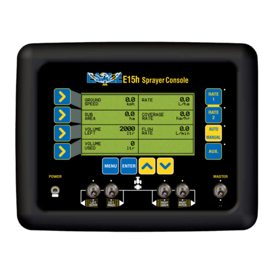
E15h SPRAYER- Console Overview V 1.0 11/05 2.0 CONSOLE OVERVIEW 2.1 WORKING SCREEN DISPLAY Ground Speed Application Rate Sub Area or Sub Area Number or Total Area Coverage Rate Volume Volume Left (Flow Rate) Volume Used Alarm Window Working Screen The above “Working Screen”... - Page 13 E15h SPRAYER- Console Overview V 1.0 11/05 Below will show all the functions that can be displayed in each window. Most of the functions will have to be enabled in the “Sprayer Setup” before the functions can be displayed in the windows. The first function listed is the default function displayed on the screen.
-
Page 14: Working Screen Button Functions
Power Switch Section Switches Power Switch The Eagle console is switched ON and OFF by this switch on the front panel. By default down is ON. Master Switch The MASTER switch turns all sections selected for operation, ON or OFF. By default down is ON Light Emitting Diode (LED). - Page 15 E15h SPRAYER- Console Overview V 1.0 11/05 SECTION SWITCHES 1. These switches turn individual Sections ON or OFF. By default down is ON 2. The red LED’s aligned above and below each section switch, indicates the status of each Section When the LED light is: •...
- Page 16 E15h SPRAYER- Console Overview V 1.0 11/05 NAVIGATION BUTTONS 1) MAIN MENU- The Navigation Buttons LINE 1, LINE 2, LINE 3 AND LINE 4) allow the operator to navigate in the MAIN MENU. LINE 1 selects line 1 of the display; LINE 2 selects line 2 of the display and so on for LINE 3 and LINE 4.
-
Page 17: Main Menu
E15h SPRAYER- Console Overview V 1.0 11/05 2.3 MAIN MENU • Press MENU. To enter the MAIN MENU screen To enter the MENU screens ensure the MASTER switch is in the OFF position. Note: All procedures assume the operator is starting from the “Working Screen”. •... -
Page 18: Setup Menu
E15h SPRAYER- Console Overview V 1.0 11/05 2.4 SETUP MENU • Press MENU. To enter OPERATIONS MENU screen • Press ENTER. To enter SETUP MENU screen • To advance to the SPRAYER SETUP MENU see Section 3.0 • To advance to the ALARMS SETUP MENU see Section 4.0 •... -
Page 19: Sprayer Setup Menu
E15h SPRAYER- Sprayer Setup Operation V 1.0 11/05 3.0 SPRAYER SETUP MENU • Press MENU • Press ENTER to select SETUP • Press ENTER to select SPRAYER SETUP Sprayer Setup Screen... -
Page 20: Set The Preset Rate
E15h SPRAYER- Sprayer Setup Operation V 1.0 11/05 SET THE PRESET RATE 1 Note: This sets the “Main Target” Rate for the sprayer, and activated by the RATE 1 button on the console. • Press MENU • Press ENTER to select SETUP •... -
Page 21: Set The Preset Row Width And Sections Widths
E15h SPRAYER- Sprayer Setup Operation V 1.0 11/05 SET THE PRESET ROW WIDTH and SECTION WIDTHS Note: This sets the Section widths of each row. 4 Preset Widths can be set. • Press MENU • Press ENTER to select SETUP •... - Page 22 E15h SPRAYER- Sprayer Setup Operation V 1.0 11/05 • With the focus on TOTAL WIDTH. Press the INC or DEC buttons, to select the Preset Width to change, (1,2,3 or 4). The current TOTAL WIDTH and ROW WIDTH will be displayed for that number. •...
-
Page 23: Set The Low Speed Shutoff
E15h SPRAYER- Sprayer Setup Operation V 1.0 11/05 SET THE LOW SPEED SHUTOFF Note: This sets the LOW SPEED SHUTOFF value, so when the boomspray slows down below this value , the boom spray will turn all sections OFF, and the sections will stay on HOLD, the regulator valve will hold the same position when the ‘Low Speed Shutoff’... -
Page 24: Set The Wheel Calibration Factor
E15h SPRAYER- Sprayer Setup Operation V 1.0 11/05 3.8 SET THE WHEEL CALIBRATION FACTOR • Press MENU • Press ENTER to select SETUP • Press ENTER to select SPRAYER SETUP • Press LINE 4 until the focus window is on SPEED CAL. The focus window displays the current SPEED CAL factor •... -
Page 25: Select Speed Source
E15h SPRAYER- Sprayer Setup Operation V 1.0 11/05 3.8.1 SELECT SPEED SOURCE • Press Line 4 to highlight SPEED SOURCE • Press ENTER. An asterisk (*) will appear. • Use INC/DEC buttons to select STANDARD or RADAR. • Press ENTER to accept changes. 3.8.2 AUTOMATIC WHEEL CALIBRATION •... -
Page 26: Set The Flow Calibration Factor
E15h SPRAYER- Sprayer Setup Operation V 1.0 11/05 3.9 SET THE FLOW CALIBRATION FACTOR • Press MENU • Press ENTER to select SETUP • Press ENTER to select SPRAYER SETUP • Press LINE 4 twice until the focus is on FLOW CAL. The focus window will display the current FLOW CAL factor in pulses/volume •... -
Page 27: Automatic Flow Calibration
E15h SPRAYER- Sprayer Setup Operation V 1.0 11/05 3.9.1 AUTOMATIC FLOW CALIBRATION • Fully prime the flow sensor and hose • Disconnect one of the section lines from the spray manifold • Place a bucket under the output of the section valve •... -
Page 28: Sprayer Setup 2 Menu
E15h SPRAYER- Sprayer Setup Operation V 1.0 11/05 3.10 SPRAYER SETUP 2 MENU • Press MENU • Press ENTER to select SETUP • Press ENTER to select SPRAYER SETUP • Press the DEC button to advance to the SPRAYER SETUP 2 screen Sprayer Setup 2 Screen... -
Page 29: Set A Manual Speed
E15h SPRAYER- Sprayer Setup Operation V 1.0 11/05 3.11 SET A MANUAL SPEED • Press MENU • Press ENTER to select SETUP • Press ENTER to select SPRAYER SETUP • Press Dec (down arrow), the screen advances to SPRAYER SETUP 2 •... -
Page 30: Enable Data Logger
E15h SPRAYER- Sprayer Setup Operation V 1.0 11/05 3.14 ENABLE DATA LOGGER Note: Only enable the ‘Data Logger’ if an optional A1920 Data Logger kit is connected to the CON 3 plug at the back of the E15h console. • Press MENU •... -
Page 31: Enable Full Row Per Section
E15h SPRAYER- Sprayer Setup Operation V 1.0 11/05 3.17 ENABLE FULL ROW PER SECTION Note: By default this function is selected OFF; therefore each section switch, switches half a row ON and OFF. When FULL ROW PER SECTION is enabled ON, then each section switch, switches 1 row ON and OFF. -
Page 32: Sprayer Setup 3 Menu
E15h SPRAYER- Sprayer Setup Operation V 1.0 11/05 3.19 SPRAYER SETUP 3 MENU • Press MENU • Press ENTER to select SETUP • Press ENTER to select SPRAYER SETUP • Press the DEC button to advance to the SPRAYER SETUP 2 screen •... -
Page 33: Enable Pump Speed Sensor
E15h SPRAYER- Sprayer Setup Operation V 1.0 11/05 3.20 ENABLE PUMP SPEED SENSOR Note: Select ON if a PUMP SPEED SENSOR is fitted to the sprayer loom, to the plug marked PUMP SPEED. The PUMP SPEED plug is only available on the ‘FULLY FEATURED HORTICULTURAL LOOM’. -
Page 34: Select Dump Mode
E15h SPRAYER- Sprayer Setup Operation V 1.0 11/05 3.23 SELECT DUMP MODE Note: If connecting a DUMP VALVE to the ‘37 Pin’ plug marked DUMP on the sprayer loom, then select STANDARD. STANDARD is the default. Normally STANDARD is selected when using a ‘Fully Featured Horticultural Loom’. If connecting the DUMP valve to the ‘24 Pin’... -
Page 35: Enable Fan Monitoring
E15h SPRAYER- Sprayer Setup Operation V 1.0 11/05 Note: If no fans are to be monitored then set FAN MONITOR to OFF and set FANS ENABLED to ‘0’ When FAN MONITOR is selected to OFF, then there is FAN MONITOR ECU fitted to the E15 h console. -
Page 36: Sprayer Setup 4 Menu
E15h SPRAYER- Sprayer Setup Operation V 1.0 11/05 3.28 SPRAYER SETUP 4 MENU • Press MENU • Press ENTER to select SETUP • Press ENTER to select SPRAYER SETUP • Press the DEC button to advance to the SPRAYER SETUP 2 screen •... -
Page 37: Enable Pressure1 Sensor
Note: PRESSURE GAIN is setting the gain for the pressure sensor connected to the plug marked “PRESSURE SENSOR” on the “Sprayer Loom”. The default is “x2” Only use “x1” if the Eagle E15h console was purchased before June 2005. • Press MENU •... -
Page 38: Pressure Sensor 1 Calibration
E15h SPRAYER- Sprayer Setup Operation V 1.0 11/05 3.32 PRESSURE SENSOR 1 CALIBRATION Pressure Cal Screen... - Page 39 • Press ENTER. The focus window will move to the next window ‘IS PUMP OFF?’ then Press ENTER. at this point the Eagle console is taking a zero point for the electronic pressure sensor while the spray pump is switched OFF.
-
Page 40: Alarms Setup Menu
E15h SPRAYER- Alarm Setup V 1.0 11/05 4.0 ALARMS SETUP MENU • Press MENU • Press ENTER to select SETUP • Press LINE 2, the focus is on ALARM SETUP • Press ENTER to select ALARM SETUP Alarms Menu Setup... -
Page 41: Rate Alarms
E15h SPRAYER- Alarm Setup V 1.0 11/05 4.1 RATE ALARMS • Press MENU • Press ENTER to select SETUP • Press LINE 2, the focus is on ALARM SETUP • Press ENTER to select ALARM SETUP • Press ENTER to select RATE ALARMS Rate Alarms Screen... - Page 42 V 1.0 11/05 E15h SPRAYER- Alarm Setup 4.1 RATE ALARMS 4.1.1 ENABLE THE MINIMUM FLOW ALARM NOTE: To set the MINIMUM FLOW value, see Section 3.3. • Press MENU • Press ENTER to select SETUP • Press LINE 2, the focus is on ALARM SETUP •...
- Page 43 E15h SPRAYER- Alarm Setup V 1.0 11/05 4.1.4 ENABLE THE APPLICATION RATE HIGH ALARM • Press MENU • Press ENTER to select SETUP • Press LINE 2, the focus is on ALARM SETUP • Press ENTER to select ALARM SETUP •...
-
Page 44: Shaft Alarms
E15h SPRAYER- Alarm Setup V 1.0 11/05 4.2 SHAFT ALARMS Shaft Alarms Screen... - Page 45 E15h SPRAYER- Alarm Setup V 1.0 11/05 NOTE: For the PUMP LOW SPEED and PUMP HIGH SPEED ALARMS to be enabled on the SHAFT ALARMS screen, the PUMP SPEED SENSOR has to be set to ON. See Section 3.22 to enable the PUMP SPEED SENSOR ON or OFF 4.2.1 ENABLE THE PUMP SPEED LOW ALARM •...
- Page 46 E15h SPRAYER- Alarm Setup V 1.0 11/05 4.2.4 SET THE PUMP SPEED HIGH ALARM POINT • Press MENU • Press ENTER to select SETUP • Press LINE 2 the focus is on ALARM SETUP • Press ENTER to select ALARM SETUP •...
- Page 47 E15h SPRAYER- Alarm Setup V 1.0 11/05 4.2.7 ENABLE THE AUX SHAFT HIGH ALARM • Press MENU • Press ENTER to select SETUP • Press LINE 2 the focus is on ALARM SETUP • Press ENTER to select ALARM SETUP •...
-
Page 48: Speed Alarms
E15h SPRAYER- Alarm Setup V 1.0 11/05 4.3 SPEED ALARMS • Press MENU • Press ENTER to select SETUP • Press LINE 2 the focus is on ALARM SETUP • Press ENTER to select ALARM SETUP • Press LINE 3, the focus is on SPEED ALARMS •... - Page 49 E15h SPRAYER- Alarm Setup V 1.0 11/05 4.3.1 ENABLE THE SPEED LOW ALARM • Press MENU • Press ENTER to select SETUP • Press LINE 2 the focus is on ALARM SETUP • Press ENTER to select ALARM SETUP • Press LINE 3, the focus is on SPEED ALARMS •...
- Page 50 V 1.0 11/05 E15h SPRAYER- Alarm Setup 4.3.4 SET THE SPEED HIGH POINT • Press MENU • Press ENTER to select SETUP • Press LINE 2, the focus is on ALARM SETUP • Press ENTER to select ALARM SETUP • Press LINE 3, the focus is on SPEED ALARMS •...
-
Page 51: Tank Alarms
V 1.0 11/05 E15h SPRAYER- Tank Alarm 4.4 TANK ALARMS • Press MENU • Press ENTER to select SETUP • Press LINE 2, the focus is on ALARM SETUP • Press ENTER to select ALARM SETUP • Press LINE 4, the focus is on TANK ALARMS •... - Page 52 E15h SPRAYER - Tank Alarms V 1.0 11/05 4.4.1 ENABLE THE VOLUME LOW ALARM • Press MENU • Press ENTER to select SETUP • Press LINE 2, the focus is on ALARM SETUP • Press ENTER to select ALARM SETUP •...
-
Page 53: Pressure Alarms
E15h SPRAYER- Pressure Alarm V 1.0 11/05 4.5 PRESSURE ALARMS • Press MENU • Press ENTER to select SETUP • Press LINE 2 the focus is on ALARM SETUP • Press ENTER to select ALARM SETUP • Press LINE 1,until the focus is on PRESSURE ALARMS •... - Page 54 E15h SPRAYER- Pressure Alarm V 1.0 11/05 4.5.1 ENABLE THE PRESSURE 1 LOW ALARM • Press MENU • Press ENTER to select SETUP • Press LINE 2 the focus is on ALARM SETUP • Press ENTER to select ALARM SETUP •...
- Page 55 E15h SPRAYER- Pressure Alarm V 1.0 11/05 4.5.4 SET THE PRESSURE 1 HIGH ALARM POINT • Press MENU • Press ENTER to select SETUP • Press LINE 2, the focus is on ALARM SETUP • Press ENTER to select ALARM SETUP •...
-
Page 56: Controller Setup Menu
E15h SPRAYER- Controller Setup V 1.0 11/05 CONTROLLER SETUP MENU • Press MENU • Press ENTER to select SETUP • Press LINE 3, the focus is on CONTROLLER SETUP • Press ENTER to CONTROLLER SETUP Controller Setup Screen... -
Page 57: Set Control Mode
E15h SPRAYER- Controller Setup V 1.0 11/05 5.1 SET CONTROL MODE Note: This setting is selecting the type of regulator valve connected to the plug marked ‘REG VALVE 1” on the “Sprayer Loom”. When the type of regulator valve is selected, the defaults are automatically set for: “MAX ON TIME”, “MIN ON TIME”, “GAIN SETTING”... -
Page 58: Set The Gain Setting
E15h SPRAYER- Controller Setup V 1.0 11/05 5.4 SET THE GAIN SETTING • Press MENU • Press ENTER to select SETUP • Press LINE 3, the focus is on CONTROLLER SETUP • Press ENTER to CONTROLLER SETUP • Press LINE 3, the focus is on GAIN SETTING •... -
Page 59: Select Close Valve When Off
E15h SPRAYER- Controller Setup V 1.0 11/05 5.7 SELECT CLOSE VALVE WHEN OFF • Press MENU • Press ENTER to select SETUP • Press LINE 3, the focus is on CONTROLLER SETUP • Press ENTER to CONTROLLER SETUP • Press LINE 4, until the focus is on CLOSE VALVE WHEN OFF •... -
Page 60: Operating History
E15h SPRAYER- Operating History V 1.0 11/05 6.0 OPERATING HISTORY • Press MENU • Press LINE 2, the focus is on OPERATING HISTORY • Press ENTER to select OPERATING HISTORY Operating History Screen... -
Page 61: Totals History
E15h SPRAYER- Operating History V 1.0 11/05 V1.1 6.1 TOTALS HISTORY • Press MENU • Press LINE 2, the focus is on OPERATING HISTORY • Press ENTER to select OPERATING HISTORY • Press ENTER to select TOTAL HISTORY Totals History Screen... - Page 62 E15h SPRAYER- Operating History V 1.0 11/05 6.1.1 RESET THE TOTAL VOLUME • Press MENU • Press LINE 2, the focus is on OPERATING HISTORY • Press ENTER to select OPERATING HISTORY • Press ENTER to select TOTAL HISTORY • Press ENTER to edit TOTAL VOLUME. An asterisk (*) will appear •...
- Page 63 V 1.0 11/05 E15h SPRAYER- Operating History 6.1.5 RESET THE TOTAL DISTANCE • Press MENU • Press LINE 2 the focus is on OPERATING HISTORY • Press ENTER to select OPERATING HISTORY • Press ENTER to select TOTAL HISTORY • Press LINE 3 the focus is on TOTAL DISTANCE •...
-
Page 64: Shaft Speed History
E15h SPRAYER- Operating History V 1.0 11/05 6.2 SHAFT SPEED HISTORY These values are display values only, they are not editable by the user Shaft Speed History Screen... -
Page 65: Machine History
E15h SPRAYER- Operating History V 1.0 11/05 E15 SPRAYER- Operating History 6.3 MACHINE HISTORY These values are display values only, they are not editable by the user V1.1 Machine History Screen... -
Page 66: Operations: Sprayer
V 1.0 11/05 E15h SPRAYER- Operations: Sprayer 7.0 OPERATIONS: SPRAYER Working Screen... -
Page 67: Operation Of The Sprayer
E15h SPRAYER- Operations: Sprayer V 1.0 11/05 7.1 OPERATION OF THE SPRAYER 7.1.1.DISPLAY THE VOLUME REMAINING IN THE TANK • VOLUME LEFT by default is displayed, on ‘Line 3’ on the left hand side of the Working Screen. If it isn’t displayed then: •... -
Page 68: To Clear A Sub Area
E15h SPRAYER- Operations: Sprayer V 1.0 11/05 7.1.7 TO CLEAR SUB AREA • Ensure the SUB AREA is displayed in the LINE 2 window. If the SUB AREA isn’t in the focus window, Press LINE 2 button and then keeping pressing the AUX button until the SUB AREA is displayed. - Page 69 E15h SPRAYER- Operations: Sprayer V 1.0 11/05 7.1.11 SELECT BETWEEN COVERAGE RATE, ROW WIDTH, PRESSURE 1 and FAN 1 SPEED NOTE: To switch between PRESSURE 1 and FAN 1 SPEED, the PRESSURE 1 SENSOR has to be enabled, ON,(see section 3.31 to set), the FAN 1 SPEED has to have at least 1 or more Fans selected in Section 3.29).
-
Page 70: Select Between Volume Left And Flush Function
E15h SPRAYER- Operations: Sprayer V 1.0 11/05 7.1.13 SELECT BETWEEN VOLUME LEFT and FLUSH FUNCTION NOTE: To enable the FLUSH FUNCTION see Section 3.16 If the FLUSH FUNCTION is disabled, then only the VOLUME LEFT will be displayed in the window. With VOLUME LEFT displayed: •... -
Page 71: Activate Flush Function
E15h SPRAYER- Operations: Sprayer V 1.0 11/05 7.1.18 ACTIVATE FLUSH FUNCTION Note: To use the FLUSH FUNCTION, then the FLUSH FUNCTION must be enabled, see Section 3.16 and set a FLUSH TIME, see Section 3.17. • Switch spray pump ON, to operating pressure. •... -
Page 72: Activate Auxiliary Function
E15h SPRAYER- Operations: Sprayer V 1.0 11/05 7.1.17 ACTIVATE AUXILIARY FUNCTION Note: To use the AUXILIARY FUNCTION, then the AUXILIARY FUNCTION must be enabled, see Section 3.20. The Auxiliary function allows a ‘Foam Marker’ or ‘Working Lights’ to be fitted to the sprayer and switched ON, or OFF from the sprayer console •... -
Page 73: To Begin Spraying
E15h SPRAYER- Operations: Sprayer V 1.0 11/05 7.2 TO BEGIN SPRAYING 7.2.1 TO BEGIN SPRAYING (Manual Mode) • Select a Sub Area Number. Reset Sub Area if necessary. • Electronically fill the tank. • Start up Pump. • Switch any required sections ON. Corresponding LED’s will flash •... -
Page 74: Operations: Data Logger
E15h SPRAYER- Operations: Data Logger V 1.0 11/05 7.3 OPERATIONS: DATA LOGGER Working Screen with Data Logger Enabled... -
Page 75: Connect The Data Logger Interface To The Eagle E15H
‘Job Number’. • Set the Eagle console to AUTO, activate the required sections, switch the Master Switch ON. and begin spraying. The pre-programmed rate will be set as the TARGET RATE. -
Page 76: Change The Job Number
E15h SPRAYER- Operations: Data Logger V 1.0 11/05 7.3.5 CHANGE THE JOB NUMBER • Connect the programmed module to the data logger interface • Set the sub area on the console to the sub area shown on the job sheet that relates to the required job number as previously described 7.3.6 SPRAY WITHOUT USING PREPROGRAMMED RATES •... -
Page 77: Configuration Options
E15h SPRAYER- Configuration Options V 1.0 11/05 8.0 CONFIGURATION OPTIONS To access the extra console related configuration options, hold down the DEC button while the unit is first starting up. • To advance to the GENERAL CONFIG see Section 8.3 •... -
Page 78: Key Configuration
E15h SPRAYER- Configuration Options V 1.0 11/05 8.1 KEY CONFIGURATION • Press LINE 2 to highlight KEY CONFIG • Press ENTER to advance KEY CONFIGURATION screen Key Configuration Screen... -
Page 79: Enable The Key Beeper On Or Off
E15h SPRAYER- Configuration Option V 1.0 11/05 8.1.1 ENABLE THE KEY BEEPER ON or OFF • Press LINE 2 to highlight KEY CONFIG • Press ENTER to advance KEY CONFIGURATION screen • Press ENTER to edit the KEY BEEPER. An asterisk (*) will be displayed •... -
Page 80: Alarm Configuration
E15h SPRAYER- Configuration Option V 1.0 11/05 8.2 ALARM CONFIGURATION • Press LINE 3 to highlight ALARM CONFIG • Press ENTER to advance to the ALARM CONFIGURATION screen. Alarm Configuration Screen... -
Page 81: Alarm Beeper Overview
E15h SPRAYER- Configuration Option V 1.0 11/05 8.2.1 Alarm Beeper Overview- • This screen allows to change the settings on how the alarm will beep when an alarm appears in the ALARM WINDOW on the Working Screen. • The ALARM CYCLE TIME sets how long in milliseconds(mS) the alarm stays in the ALARM WINDOW. -
Page 82: Set The Alarm Cycle Time
E15h SPRAYER- Configuration Option V 1.0 11/05 8.2.2 SET THE ALARM CYCLE TIME • Press LINE 3 to highlight ALARM CONFIG • Press ENTER to advance to the ALARM CONFIGURATION screen • Press ENTER to edit the ALARM CYCLE TIME. An asterisk (*) will be displayed •... -
Page 83: General Configuration
E15h SPRAYER- Configuration Option V 1.0 11/05 8.3 GENERAL CONFIGURATION • Press LINE 1 to select GENERAL CONFIG • Press ENTER to select GENERAL CONFIG • To advance to the DIAGNOSTICS MODE see Section 9.0 8.3.1 COLD RESET • Press Line 2 to select COLD RESET •... -
Page 84: Switch Configuration
E15h SPRAYER- Configuration Option V 1.0 11/05 8.4 SWITCH CONFIGURATION Note: The default is for the TOGGLE UP ACTIVE to be OFF. Therefore when the Section and Master switches are switched ON, the switches are in the down position. When the TOGGLE UP ACTIVE is selected ON, then when the Section and Master switches are ON they in the UP position. -
Page 85: Diagnostics Mode
E15h SPRAYER- Diagnostics Mode V 1.0 11/05 9.0 DIAGNOSTICS MODE • Hold the DEC button down(for about 5 seconds) while turning the console POWER button ON. • Press ENTER to advance to the GENERAL CONFIG screen • Press LINE 1 to highlight DIAGNOSTICS MODE •... -
Page 86: Led Test
E15h SPRAYER- Diagnostics Mode V 1.0 11/05 9.1 LED TEST • Select this to check the operation of the Light Emitting Device (LED)’s on the front panel. Diagram below shows the positions of the LED,s • If operating correctly the LED’s will cycle consecutively around the front panel, starting from the: 1)- Right hand side of console from top to bottom, 2)- The LED’s above the Section switches from left to right. -
Page 87: Switch Test
E15h SPRAYER- Diagnostics Mode V 1.0 11/05 9.2 SWITCH TEST • Select this to check the operation of the switches • If operating correctly: • The MASTER switch when in the OFF position; “MASTER SWITCH = OFF will be displayed on the console screen •... -
Page 88: Keys Test
V 1.0 11/05 E15h SPRAYER- Diagnostics Mode 9.3 KEYS TEST • Select this to check the operation of the buttons on the front panel • Press any button and the button that is ‘pressed’, will be displayed on the console screen •... -
Page 89: Sensors Test
E15h SPRAYER- Diagnostics Mode V 1.0 11/05 9.4 SENSORS TEST • Select this test to check the operation of the sensor circuitry • The current period (time between pulse, measured in mS) for each sensor will be displayed on the screen. •... -
Page 90: Checking Loom Voltages, For 3 Pin Sensors
E15h SPRAYER- Diagnostics Mode V 1.0 11/05 9.4.1CHECKING LOOM VOLTAGES, FOR 3 PIN SENSORS • This test should be carried out if the sensor (ground speed sensor, flow meter sensors, ) that appears to be faulty has been checked using the Diagnostic Test in Section 9.4., and no ‘pulse count’, or no ‘period’... -
Page 91: Relays Test
E15h SPRAYER- Diagnostics Mode V 1.0 11/05 9.5 RELAYS TEST • Select this to check the operation of the relay circuitry • This test, cycles through each relay within the console; and each of the three states of each relay •... -
Page 92: Regulator Valve Test
• Select this to check the operation of the REGULATOR valve • The value will automatically open and close • Check the regulating valve on the sprayer is opening when the Eagle console says it is opening and closing when the Eagle console says it is closing. -
Page 93: Eeprom Test
E15h SPRAYER- Diagnostics Mode V 1.0 11/05 9.7 EEPROM TEST • Select this to check the operation of the read/write to memory chip. • When on the memory test page, the lines will keep scrolling. If it stops on a particular line, there is a problem, and the information is not being saved properly to the memory chip in the console. -
Page 94: Alarm Messages
E15 SPRAYER- Alarm Messages V 1.0 11/05 10.0 ALARM MESSAGES 10.1 Alarm Messages Overview All alarms that are present, will flash in the ‘Alarm Window’. to alert the operator. The frequency and whether an alarm sounds when an alarm is displayed in the ‘Alarm Window’, is set in the ALARM CONFIGURATION, see Section 8.2. -
Page 95: Alarm Messages
E15 SPRAYER- Alarm Messages V 1.0 11/05 10.2 ALARM MESSAGES LOW SPEED SHUTOFF- This alarm will come when no ground speed has been detected, or the ground speed is below the value set in the LOW SPEED SHUTOFF (See Section 3.5 to set). The boomspray will not spray when this alarm is displayed. - Page 96 E15h SPRAYER- Alarm Messages V 1.0 11/05 PUMP SPEED LOW - This alarm will be displayed when the sensor installed on the shaft of the pump, and the rpm of the shaft falls below the alarm point. See section 4.2.2 to set PUMP SPEED LOW alarm point. To rectify problem increase the pump speed up to operating speed for the pump.
- Page 97 DATA LOGGER IS NOT FOUND- This alarm will be displayed when the DATA LOGGER is enabled in Section 3.14, but the Eagle has detected there is no Data Logger connected to CON 3 on the back of the Eagle console.
-
Page 98: Specifications
V 1.2 Major Topic Heading E15h SPRAYER- Specifications V 1.0 11/05 11. SPECIFICATIONS 11.1 CONSOLE • Supply Voltage 12.5 - 16 volts Negative earth system. The Console’s power leads must be connected directly to the tractors battery terminals. No attempt should be made to connect the system to positive earth vehicle. Damage will result and Warranty will become void. - Page 99 E15h SPRAYER- Specifications V 1.0 11/05 11.3.2 Polmac • 3 Wire Flow Sensor • Flow Rate: 20 - 200 l/min • Calibration: approx: 630 pulse/l • Accuracy: +/- 1% when flow is 10-100 l/min +/- 3 % when flow is 100 - 200 l/min •...
-
Page 100: Economy Looms
E15h SPRAYER- Wiring Diagrams-Console Pin outs (Economy V 1.0 11/05 12.1 ECONOMY LOOMS... -
Page 101: Tractor Loom
E15h SPRAYER- Wiring Diagrams -Tractor Loom (Economy Looms) V 1.0 11/05... -
Page 102: Tractor Loom
E15h SPRAYER- Wiring Diagrams -Sprayer Loom (Economy Looms) V 1.0 11/05... -
Page 103: Sprayer Loom
E15h SPRAYER- Wiring Diagrams -Sprayer Loom (Economy Looms) V 1.0 11/05... -
Page 104: Mk5 To E15H Adaptor Loom
E15h SPRAYER- Wiring Diagrams -Sprayer Loom (Economy Looms) V 1.0 11/05... - Page 105 Personal Notes...
- Page 106 V 1.2 Major Topic Heading Personal Notes...
- Page 107 V 1.2 Major Topic Heading Personal Notes...