
Related Manuals for Ventrac KH500 Versa-Loader

Summary of Contents for Ventrac KH500 Versa-Loader
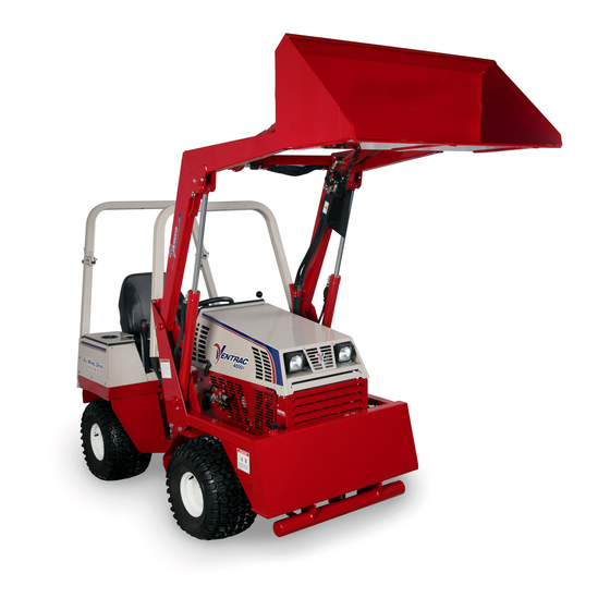
- Page 1 Operator’s Manual & Parts Drawings KH500 Versa-Loader Serial Number KH500-AA1280 -- VENTRAC.COM Revised 02/27/19 Original Operator’s Manual 09.10079 Rev. 03...
- Page 2 To the Owner Contact Information and Product Identification If you need to contact an authorized Ventrac dealer for information on servicing your product, always provide the product model and serial numbers. Please fill in the following information for future reference. See the picture(s) below to find the location of the identification numbers.
-
Page 3: Table Of Contents
TABLE OF CONTENTS INTRODUCTION PAGE 5 Product Description ..........................5 Why Do I Need an Operator’s Manual? ....................5 Using Your Manual ..........................6 Manual Glossary ............................6 SAFETY PAGE 7 Safety Decals ............................7 General Safety Procedures ........................9 Training Required ...........................9 Personal Protective Equipment Requirements ..................9 Operation Safety ............................9 Preventing Accidents ..........................10 Keep Riders Off ............................10... - Page 4 TABLE OF CONTENTS SPECIFICATIONS PAGE 24 Dimensions ............................24 Features ...............................24 PARTS PAGE 26 Main Frame, Loader Arms, & Crossbar Mount ..................26 Tool Attachment Mount .........................28 Hydraulic Pump & Valve ........................30 Hydraulic Lift ............................32 Hydraulic Tilt ............................34 Pallet Fork Attachment .........................36 Hydraulic Diagram ..........................38 WARRANTY PAGE 40...
-
Page 5: Introduction
Ventrac dealer for a replacement. When using a Ventrac attachment, be sure to read and follow the safety and operating instructions of both the power unit and the attachment being used to ensure the safest operation possible. -
Page 6: Using Your Manual
Manual Glossary Power Unit A Ventrac tractor or other Ventrac engine powered device that may be operated by itself or with an attachment or accessory. Attachment A piece of Ventrac equipment that requires a Power Unit for operation. -
Page 7: Safety
SAFETY Safety Decals The following safety decals must be maintained on your KH500 versa-loader. Keep all safety decals legible. Remove all grease, dirt, and debris from safety decals and instructional labels. If any decals are faded, illegible, or missing, contact your dealer promptly for replacements. - Page 8 SAFETY Decal Description Part Number Quantity Danger, Loader 00.0193 Warning, Read Owner’s Manual 00.0217 Warning, Loader 00.0410 Warning, Loader Rollbar 00.0194 Warning, Hot Surface 00.0374 Safety - 8...
-
Page 9: General Safety Procedures
SAFETY General Safety Procedures for Ventrac Power Units, Attachments, & Accessories Training Required • The owner of this machine is solely responsible for properly training the operators. • The owner/operator is solely responsible for the operation of this machine and prevention of accidents or injuries occurring to him/her- self, other people, or property. -
Page 10: Preventing Accidents
SAFETY General Safety Procedures for Ventrac Power Units, Attachments, & Accessories Operation Safety (continued) • If equipped with a high/low range feature, never shift between high and low range while on a slope. Always move the machine to level ground and engage the parking brake before shifting range. -
Page 11: Operating On Slopes
SAFETY General Safety Procedures for Ventrac Power Units, Attachments, & Accessories Operating On Slopes • Slopes can cause loss-of-control and tip-over accidents, which can result in severe injury or death. Be familiar with the emergency parking brake, along with the power unit controls and their functions. -
Page 12: Maintenance
• If the power unit, attachment, or accessory requires repairs or adjustments not instructed in the operator’s manual, the power unit, attachment, or accessory must be taken to an authorized Ventrac dealer for service. • Never perform maintenance on the power unit and/or attachment if someone is in the operator’s station. -
Page 13: Hydraulic Safety
SAFETY General Safety Procedures for Ventrac Power Units, Attachments, & Accessories Fuel Safety (continued) • Do not overfill fuel tank. Only fill to bottom of fuel neck, do not fill fuel neck full. Overfilling of fuel tank could result in engine flooding, fuel leakage from the tank, and/or damage to the emissions control system. -
Page 14: Kh500 Safety Procedures
Lower the loader to the ground before leaving the operator’s seat. • Additional rear counterweight must be used when operating the loader. Use a Ventrac accessory weight bar equipped with six Ventrac weights. Accessory weight bars are listed in the introduction section of this manual. •... -
Page 15: Operational Controls
OPERATIONAL CONTROLS Joystick Control Valve Tool Bar Locking Lever The tool bar locking lever (C) engages and disen- The joystick control valve (A) controls the functions gages the pins that lock the tool to the tool attach- of the loader. ment mount. -
Page 16: General Operation
GENERAL OPERATION Daily Inspection 4. Raise the front hitch until the rear loader mount brackets engage the rear anchor mounting shaft. NOTE: keep the rear anchor lock plates clear of the shaft to allow it to engage with the mating surfaces on the rear loader mount brackets. -
Page 17: Detaching Loader From Power Unit
10. Install counterweights on the rear of the power 14. Remove the cylinder prop pins, lift the cylinder unit (six Ventrac weights or 250 pounds (113 kg). stop props up to the operating position, and reinstall the cylinder prop pins. -
Page 18: Attaching Tool To Loader
GENERAL OPERATION Attaching Tool to Loader 6. Push the loader joystick forward until it locks into the float position and allows the loader arms to 1. Move the tool bar locking lever to the left to lower until the cylinder prop stops contact the retract the locking pins. -
Page 19: Operating Procedures
GENERAL OPERATION Operating Procedures Prior to operation, perform daily inspection and shift the power unit into low range. The roll bar must be locked in the upright position and the operator must wear a seat belt during loader operation. The added length and weight of the loader affects turning ability and increases stopping distance. -
Page 20: Service
Inspecting the drive belt of the loader can prevent notches on the dipstick. sudden belt failure by finding problems before they 6. If hydraulic oil level is low, add Ventrac Hydro- cause a belt to break. Torq XL synthetic hydraulic oil until the proper Typical wear level is reached. -
Page 21: Changing Hydraulic Oil Filter
SERVICE Lubrication Locations 9. Clean up any spilled oil and dispose of oil in accordance with local laws. Lubrication is required at the following locations CAUTION using a lithium complex NLGI #2 grease. Refer to the maintenance schedule for service intervals and amount of grease. -
Page 22: Storage
SERVICE Storage Preparing the Loader for Storage 1. Clean the loader. 2. Inspect for loose or missing hardware, damaged components, or signs of wear. 3. Inspect safety decals. Replace any safety decals that are faded, illegible, or missing. 4. Inspect hydraulic hoses and fittings to ensure tight, leak free connections. -
Page 23: Maintenance Schedule
SERVICE Maintenance Schedule Maintenance Schedule Grease & Lubrication: See Lubrication Section Cylinder Ends Loader Arm Pivots Hydraulic System Check Hydraulic Oil Level ... -
Page 24: Specifications
Hydraulic Oil Capacity ......8-1/4 gallons (31.2 liters) Features Ventrac mount system Quick attach tool attachment mount... - Page 25 Blank Page Specifications - 25...
-
Page 26: Parts
PARTS ILLUSTRATED DRAWING Main Frame, Loader Arms, & Crossbar Mount Use only original Ventrac Illustrated Parts - 26 replacement parts. - Page 27 39 ..29.P06H ....PIPE, PLUG 3/8 HEX ZP ........... 1 Use only original Ventrac Illustrated Parts - 27 replacement parts.
-
Page 28: Tool Attachment Mount
PARTS ILLUSTRATED DRAWING Tool Attachment Mount Use only original Ventrac Illustrated Parts - 28 replacement parts. - Page 29 17 ..62.0950 ....BUCKET, STANDARD 5 CUBIC FT ......... . . 1 Use only original Ventrac Illustrated Parts - 29 replacement parts.
-
Page 30: Hydraulic Pump & Valve
PARTS ILLUSTRATED DRAWING Hydraulic Pump & Valve Use only original Ventrac Illustrated Parts - 30 replacement parts. - Page 31 51 ..93.04H-3 ....NUT, HEAVY 1/4-28 SS........... . . 1 Use only original Ventrac Illustrated Parts - 31 replacement parts.
-
Page 32: Hydraulic Lift
PARTS ILLUSTRATED DRAWING Hydraulic Lift Use only original Ventrac Illustrated Parts - 32 replacement parts. - Page 33 15 ..05.0056 ....GROMMET, 2-1/8ID,2-7/8OD,7/16T ......... . . 1 Use only original Ventrac Illustrated Parts - 33 replacement parts.
-
Page 34: Hydraulic Tilt
PARTS ILLUSTRATED DRAWING Hydraulic Tilt Use only original Ventrac Illustrated Parts - 34 replacement parts. - Page 35 29 ..00.0374 ....DECAL, HOT SURFACE ........... 1 Use only original Ventrac Illustrated Parts - 35 replacement parts.
-
Page 36: Pallet Fork Attachment
PARTS ILLUSTRATED DRAWING Pallet Fork Attachment Use only original Ventrac Illustrated Parts - 36 replacement parts. - Page 37 7 ..62.0965 ....FORK, PALLET ............2 Use only original Ventrac Illustrated Parts - 37 replacement parts.
-
Page 38: Hydraulic Diagram
PARTS ILLUSTRATED DRAWING Hydraulic Diagram Use only original Ventrac Illustrated Parts - 38 replacement parts. - Page 39 13 ..20.0193 ....HOSE, 1/4X44.50 SAE 100R17 AR ......... . . 1 Use only original Ventrac Illustrated Parts - 39 replacement parts.
-
Page 40: Warranty
4000 Series Tractors & Attachments 2-year All Ventrac add-on kits and accessories such as: 3-point hitch, 12V front & rear power outlets, foot pedal, dual wheel kit, etc., will be covered under the above warranty periods provided they are installed by an Authorized Ventrac Dealer. - Page 41 (i) expenses relating to gasoline, oil, lubricants; (ii) loss, cost or expense relating to transportation or delivery of turf equipment from the location of owner or location where used by owner to or from any Authorized Ventrac Dealer; (iii) travel time, overtime, after hours’ time or other extraordinary repair charges or charge relating to repairs or replacements outside of normal business hours at the place of business of an Authorized Ventrac Dealer;...
Need help?
Do you have a question about the KH500 Versa-Loader and is the answer not in the manual?
Questions and answers